Pipette tip

A liquid pipetting and liquid storage chamber technology, applied in the field of pipetting guns, can solve the problems of inserting the handle of the pipette gun into the pipette tip, damage to the pipette tip, inaccurate experimental data, etc. Good versatility, anti-pollution, easy to use effects

Active Publication Date: 2017-10-10
南京公汇科技有限公司
View PDF6 Cites 0 Cited by
  • Summary
  • Abstract
  • Description
  • Claims
  • Application Information

AI Technical Summary

Problems solved by technology

[0003] (1) The seal between the pipette holster handle and the pipette tip is poor, and dripping will occur after absorbing liquid;
[0004] (2) The inner wall of the pipette tip is smooth, and the friction between it and the handle of the pipette gun is small. After the liquid is absorbed, the pipette tip is easy to loosen and falls off from the handle of the pipette gun, and the use stability is poor;
[0005] (3) In order to ensure the tightness between the pipette tip and the handle of the pipette holster, a large force is required during assembly, which will cause the wear of the handle of the pipette holster and affect the sealability. In addition, it is easy to Cause the pipette holster handle to be excessively inserted into the pipette head, causing damage to the pipette head;
[0006] (4) In the process of pipetting out, if the withdrawal speed is too fast, the pipette will be quickly drawn back into the pipette tip and pollute the handle of the pipette gun, which will cause pollution to the next pipetting
[0007] Moreover, during the use of the pipette, the tips of the pipette need to be replaced frequently. Once a pipette tip is polluted, the pipette will be polluted, and then all subsequent pipette tips will be polluted, which will Cause cross-contamination, which makes the experimental data inaccurate

Method used


Image

  • Pipette tip

Examples


Embodiment Construction

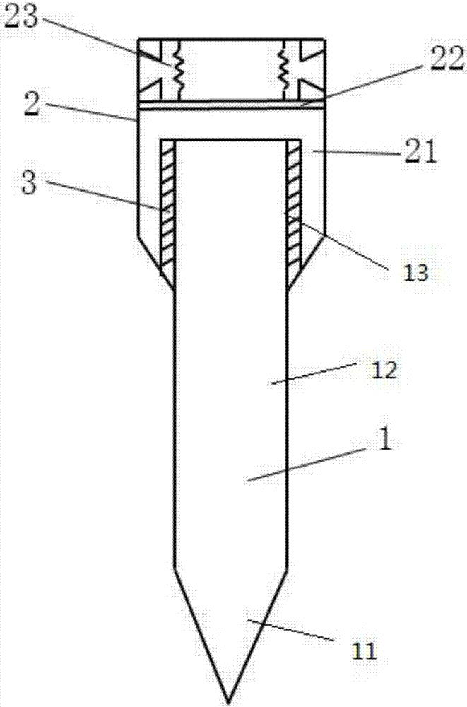
[0022] The present invention will be further described below in conjunction with the accompanying drawings.

[0023] figure 1 It is a structural schematic diagram of the present invention. Such as figure 1 As shown, the pipette head of the present invention includes a first pipette head 1 and a second pipette head 2 . The first pipette tip 1 includes a beak-shaped liquid suction end 11 connected in sequence, a liquid storage chamber 12 with a uniform diameter, and a tip tail 13; the tip tail 13 is sealed, and several filters are arranged on its side. hole 3, a filter layer is provided outside the filter hole 3, through which the pollutants inside the first pipette tip 1 are blocked in the first pipette tip 1, and will not enter the second Inside the pipette tip 2.

[0024] The second pipette tip 2 includes a cover 21, a filter layer 22 and a connecting groove 23; the cover 21 is sleeved outside the tip tail 13 of the first pipette tip 1, and the second The pipette tip 2 c...


PUM


Abstract

The invention provides a pipette tip. The pipette tip comprises a first pipette tip body (1) and a second pipette tip body (2), wherein the first pipette tip body (1) comprises a sharp liquid absorbing end (11), a tubular liquid storage cavity (12) and a tip tail part (13) which are sequentially communicated; the top of the tip tail part (13) is sealed, and a plurality of filter holes (3) are formed in the side face of the tip tail part (13); the second pipette tip body (2) comprises a cover body (21), a filter layer (22) and connecting grooves (23); the cover body (21) is arranged outside the tip tail part (13) of the first pipette tip body (1) in a sleeving manner; the filter layer (22) is arranged between the connecting groove (23) and the cover body (21); two grooves are formed in two sides of the tail end of the second pipette tip body (2), and the connecting grooves are embedded into the grooves. The pipette tip can be used for effectively solving the problems of sealing performance between the pipette tip and a pipette socket and poor use stability of the pipette, and can be used for effectively preventing pollution by setting double filter layers.

Description

technical field [0001] The invention relates to the field of pipette guns, in particular to a pipette tip. Background technique [0002] The pipette gun is a kind of pipette, which is often used for pipetting a small amount or a small amount of liquid in the laboratory. Pipette guns of different specifications are matched with corresponding pipette tips. Existing pipette tips are mostly made of polypropylene material, which has the following problems: [0003] (1) The seal between the pipette holster handle and the pipette tip is poor, and dripping will occur after absorbing liquid; [0004] (2) The inner wall of the pipette tip is smooth, and the friction between it and the handle of the pipette gun is small. After the liquid is absorbed, the pipette tip is easy to loosen and falls off from the handle of the pipette gun, and the use stability is poor; [0005] (3) In order to ensure the tightness between the pipette tip and the handle of the pipette holster, a large force...

Claims


Application Information

Patent Timeline
IPC IPC(8): B01L3/02
Inventor 李路
Owner 南京公汇科技有限公司
Why Eureka
Try Eureka