Sliding-in type fixing structure of rigid plates

A technology for fixing structures and rigid plates, applied in the direction of thin plate connections, connecting components, mechanical equipment, etc., can solve problems such as breakage and bolt bending, and achieve the effects of easy operation, reduced friction, and guaranteed accuracy

Pending Publication Date: 2019-07-19
裴前东
View PDF12 Cites 1 Cited by
  • Summary
  • Abstract
  • Description
  • Claims
  • Application Information

AI Technical Summary

Problems solved by technology

[0003] Therefore, the technical problem to be solved by the present invention is to overcome the defects in the prior art that the bolts are bent or even broken due to the uneven stress of the bolts, so as to provide a bolt that can make the bolts evenly stressed and not easy to bend. Rigid panel connection structure even broken and rigid cabinet with it

Method used


Image

  • Sliding-in type fixing structure of rigid plates
  • Sliding-in type fixing structure of rigid plates
  • Sliding-in type fixing structure of rigid plates

Examples


Embodiment 1

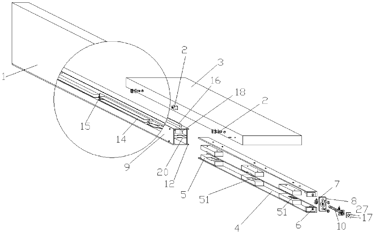
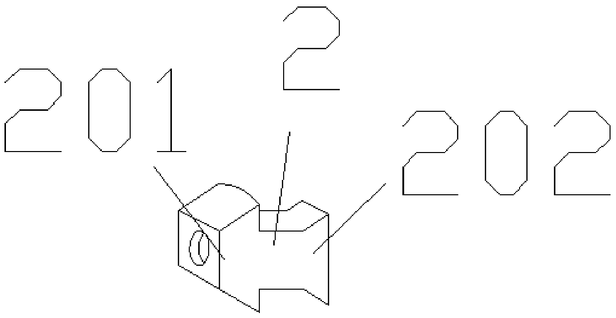
[0035] like Figure 1-9 As shown, the embodiment of the present invention provides a fixing structure for a slide-in rigid plate body, including: a fixing part 2, which is arranged in the first rigid plate body 3 to be connected; at least one set of Body 3 and the clamping member 5 arranged opposite to the connection direction of the second rigid plate body 1, the clamping member 5 is arranged in the second rigid plate body 1 to be connected, the movement direction of the clamping member 5 is in line with the The connection direction of the first rigid board 3 and the second rigid board 1 intersects, and grooves are provided on the opposite surfaces of the two clamping parts 5 to allow the fixing part 2 to slide in laterally. 51, the bottom wall of the groove body 51 is set on a slope, so that when the clamping member 5 moves, it drives the fixing member 2 to slide from low to high along the slope, and the first rigid plate body 3 and the second rigid plate body 1 apply a for...

Embodiment 2

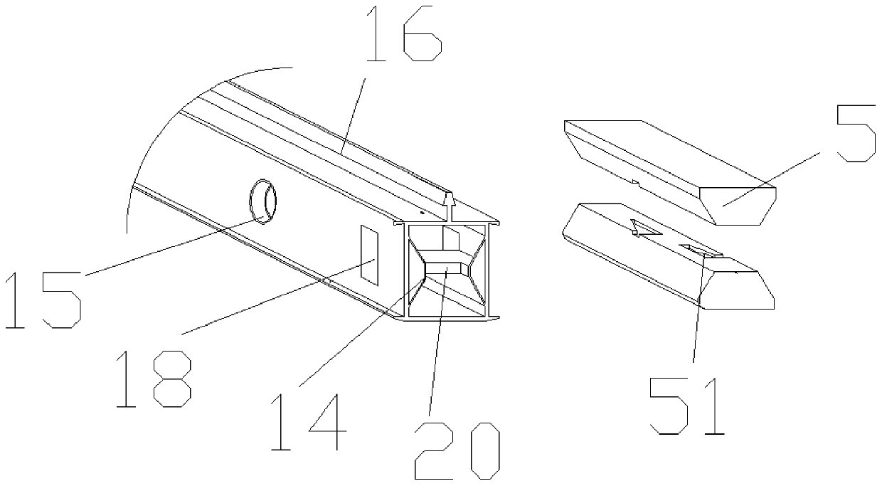
[0056] like Image 6 As shown, the longitudinal section of the clamping member 5 is "U"-shaped, including a first plate body 52, a second plate body 53 and a third plate body 54 connected in sequence, and the groove body 51 is formed on the first plate body. On the side walls of the three boards 54 , the edge of the third board 54 is formed with a riser 55 that allows the fixing member 2 to slide along with the movement of the third board 54 . Other structures are the same as in Embodiment 1.

[0057] The clamping member 5 is integrally formed, and the first plate body 52, the second plate body 53 and the third plate body 54 are sequentially connected into a "U"-shaped structure, and the groove body 51 is formed on the side wall of the third plate body 54. The semicircular opening, and the rising part 55 that is adjacent to the semicircular opening. In this embodiment, the two clamping parts 5 are symmetrically arranged, and the groove body 51 is surrounded into a circular op...

Embodiment 3

[0061] like Figure 7 As shown, a sliding piece 21 is provided on the side wall of the clamping piece 5 to reduce the frictional force when it slides into the second rigid plate body 1, and the sliding piece 21 is connected to the second rigid plate body. The groove 22 on the inner wall of the body 1 is suitable. Other structures are the same as in Embodiment 1.

[0062] In this embodiment, the fixing part 8 is directly connected to the clamping part 5, the connecting plate 4 is omitted, and the groove body 51 is formed on the clamping part 5 at predetermined intervals. The cross section of the clamping part 5 is elliptical. A plurality of sliding parts 21 are arranged at predetermined intervals on the side wall of the connecting part 5, and grooves 22 adapted to the sliding parts 21 are formed on the side wall of the pipe body 9, which mainly plays a role in reducing the clamping part 5 in the pipe body. 9 The internal sliding friction makes the operation more labor-saving....


PUM


Abstract

The invention relates to the technical field of rigid plate installation, in particular to a sliding-in type fixing structure of rigid plates. The sliding-in type fixing structure of the rigid platescomprises a fixing piece which is arranged in the first rigid plate to be connected, at least one set of clamping pieces which are oppositely arranged in the connection direction of the first rigid plate and the second rigid plate, the clamping pieces are arranged in the second rigid plate to be connected, the movement directions of the clamping pieces intersect with the connection direction of the first rigid plate and the second rigid plate, opposite faces of the two clamping pieces are both provided with grooves allowing the fixing piece to slide in laterally, the bottom walls of the grooves are slopes so that when the clamping pieces move, the clamping pieces can drive the fixing piece to slide along the slopes from the bottom to the top, and action force close to each other in the connection direction is exerted on the first rigid plate and the second rigid plate. By means of the rigid plate connection structure and a rigid cabinet with the same, the stress of bolts is uniform, the bolts are not prone to being bent or even broke off.

Description

technical field [0001] The invention relates to the technical field of rigid board installation, in particular to a fixing structure of a slide-in rigid board. Background technique [0002] At present, with the improvement of people's living standards, people have higher and higher requirements for the connection firmness of rigid cabinet products. There are usually two ways to install the two boards of the existing rigid cabinet body. One way is to directly weld the two rigid boards to be connected. Under the change of external environment, such as unavoidable vibration or shock, the firmness of the weld will become poor; another way is that the bolts directly pass through the two rigid plates to be connected. Or when worn for a long time, due to the uneven force of the bolts, it is easy to cause the bolts to bend or even break. Contents of the invention [0003] Therefore, the technical problem to be solved by the present invention is to overcome the defects in the pri...

Claims


Application Information

Patent Timeline
Patent Type & Authority Applications(China)
IPC IPC(8): F16B5/00
CPCF16B5/0024
Inventor 裴前东
Owner 裴前东
Why Eureka
Try Eureka