
Wireless communication-based modularized automatic cable checking device

A wireless communication and modularization technology, applied in the direction of measuring devices, instruments, measuring electronics, etc., can solve problems such as difficulty in meeting calibration requirements, non-one-to-one correspondence between output signals and collection results, and inconsistent number of pins

Inactive Publication Date: 2019-07-19
宋韫犀
View PDF0 Cites 0 Cited by
  • Summary
  • Abstract
  • Description
  • Claims
  • Application Information

AI Technical Summary

Problems solved by technology

[0005] 2) The output signal and the collection result are not in one-to-one correspondence;
[0006] 3) The number of pins of each output device and input device is inconsistent;
[0007] The above-mentioned traditional alignment method is difficult to meet the alignment requirements

Method used


Image

  • Wireless communication-based modularized automatic cable checking device
  • Wireless communication-based modularized automatic cable checking device
  • Wireless communication-based modularized automatic cable checking device

Examples


Embodiment 1

[0086] according to figure 1 , figure 2 , image 3 , Figure 4 , Figure 5 Describe this embodiment:

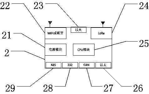
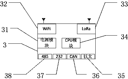
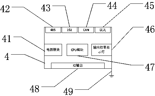
[0087] In specific embodiment 1, the modularized automatic calibration device based on wireless communication provided by the present invention, such as figure 1 , figure 2 , image 3 and Figure 4 As shown, the automatic calibration device includes a terminal display module 1, a wireless master module 2, a plurality of wireless slave modules 3, a plurality of output modules 4 and a plurality of acquisition modules 5.

[0088] In specific embodiment 1, such as figure 1 As shown, the wireless main module 2 provided by the present invention includes a power supply module 21, a WiFi or Bluetooth module 22, an Ethernet interface 23 required for wired connection with the terminal display module 1, a LoRa module 24, a CPU module 25, and an output module 4 Or the Ethernet interface 26 required for the connection of the input module 5, the CAN interface 27 required for con...


PUM


Abstract

The invention discloses a wireless communication-based automatic cable alignment device. The device comprises a terminal display module, a wireless primary module, a wireless secondary module, an output module and an acquisition module, wherein the terminal display module and the wireless primary module are wirelessly connected by adoption of WiFi or Bluetooth; the wireless primary module and thewireless secondary module are connected by adoption of LoRa, or the terminal display module and the wireless secondary module are connected by adoption of WiFi; the wireless primary module and the output module or the acquisition module are in wired connection by adoption of CAN, 485, 232 or an Ethernet; and the wireless secondary module and the output module or the acquisition module are in wiredconnection by adoption of the CAN, 485, 232 or the Ethernet. The terminal display module controls the level of pins in the output module one by one; acquisition results are returned through the acquisition module; and the terminal display module carries out matching verification. The device has the beneficial effects that one-to-one corresponding cable structures can be automatically detected andmarked without accessing wiring harnesses in the cables to the interfaces of the input and acquisition modules according to fixed numbers, so that the detection time is greatly shortened.

Description

technical field [0001] The invention relates to the fields of vehicle manufacturing, multi-core cable lines and equipment detection in power systems, in particular to the system-level detection of equipment with multiple interfaces, long distances, and passing through junction boxes and splitters. Background technique [0002] There are a large number of multi-core cables in vehicle manufacturing and power systems. The above-mentioned multi-core cables will also pass through many junction boxes and splitters, with long distribution distances and many interfaces. At present, the commonly used method is to use a multimeter (or light) to check the on-off. For long-distance lines connected by multiple junction boxes like EMUs, or multi-core cables that span houses in similar power systems, it is necessary for staff at both ends of the cable to assist with communication devices such as walkie-talkies or mobile phones. Due to the noisy environment on site, complicated and chaotic...

Claims


Application Information

Patent Timeline
Patent Type & Authority Applications(China)
IPC IPC(8): G01R31/02
CPCG01R31/60
Inventor 宋韫犀王田原野
Owner 宋韫犀
Learn More