A self-generating wireless switch
A wireless switch and self-generating technology, applied in the direction of electric switches, circuits, electrical components, etc., can solve problems such as inconsistent pressing force, achieve the effect of reducing linkage, simple structure, and increasing torque
- Summary
- Abstract
- Description
- Claims
- Application Information
AI Technical Summary
Problems solved by technology
Method used
Image
Examples
Embodiment 1
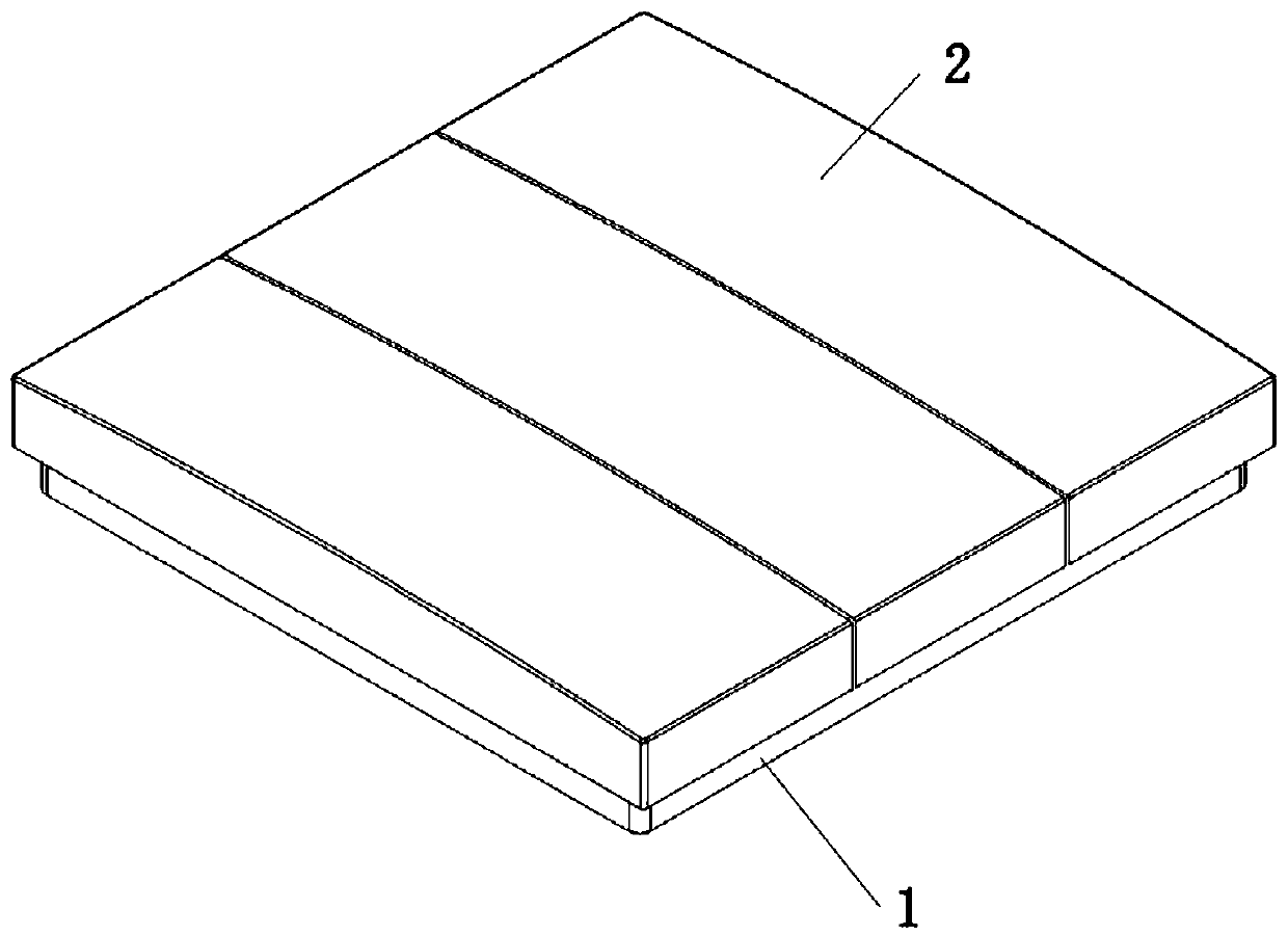
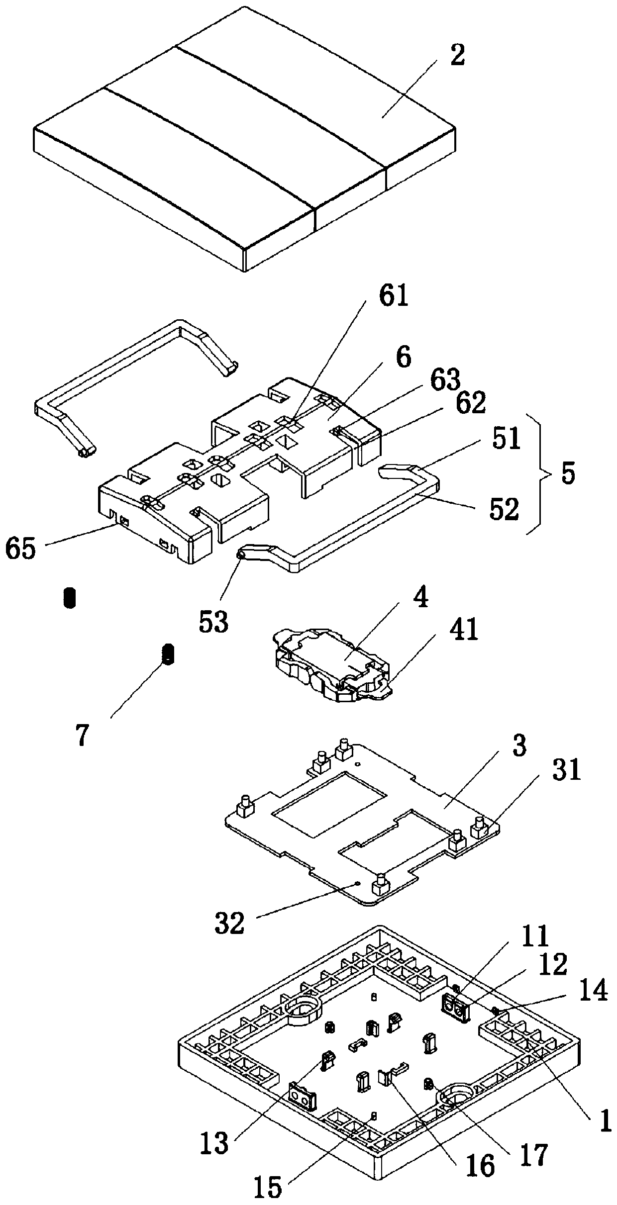
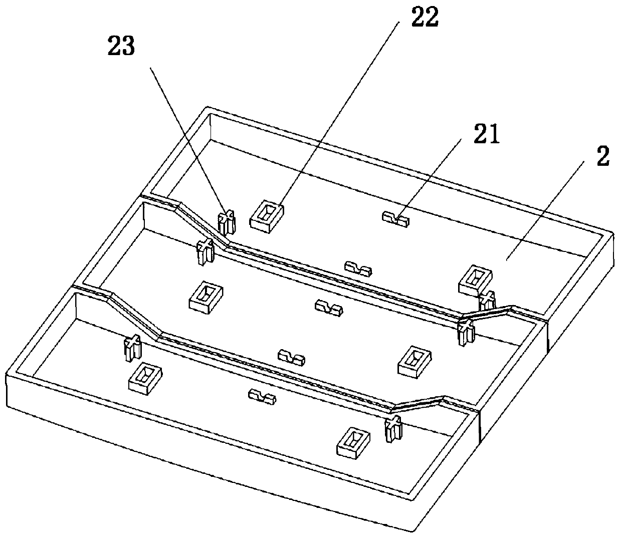
[0032] Such as Figure 1-Figure 5 As shown, the embodiment of the present invention discloses a self-generating wireless switch, including a base 1, a button 2, a circuit board 3 fixed on the base 1, and a power generation module 4, and the circuit board 3 and the power generation module 4 are electrically connected, and the opposite sides of the power generation module 4 are respectively provided with shrapnels 41 for triggering power generation switches, and are respectively located below the two ends of the button 2;
[0033] A pair of independent pressing arms 5 are symmetrically arranged on the base 1, and the pressing arms 5 include a connecting portion 51 and a supporting portion 52 connected to each other, and the end of the connecting portion 51 is connected to the The base 1 is pivotally connected, and the support part 52 is arranged between the button 2 and the shrapnel 41 of the trigger generator switch;
[0034] The base 1 is also fixedly provided with a gland 6 ...
Embodiment 2
[0045] Such as Figure 1-Figure 5 As shown, the embodiment of the present invention discloses a self-generating wireless switch, including a base 1, a button 2, a circuit board 3 fixed on the base 1, and a power generation module 4, and the circuit board 3 and the power generation module 4 are electrically connected, and the opposite sides of the power generation module 4 are respectively provided with shrapnels 41 for triggering power generation switches, and are respectively located below the two ends of the button 2;
[0046] A pair of independent pressing arms 5 are symmetrically arranged on the base 1, and the pressing arms 5 include a connecting portion 51 and a supporting portion 52 connected to each other, and the end of the connecting portion 51 is connected to the The base 1 is pivotally connected, and the support part 52 is arranged between the button 2 and the shrapnel 41 of the trigger generator switch;
[0047] The base 1 is also fixedly provided with a gland 6 ...
Embodiment 3
[0053] Such as Figure 1-Figure 6 As shown, the embodiment of the present invention discloses a self-generating wireless switch, including a base 1, a button 2, a circuit board 3 fixed on the base 1, and a power generation module 4, and the circuit board 3 and the power generation module 4 are electrically connected, and the opposite sides of the power generation module 4 are respectively provided with shrapnels 41 for triggering power generation switches, and are respectively located below the two ends of the button 2;
[0054] A pair of independent pressing arms 5 are symmetrically arranged on the base 1, and the pressing arms 5 include a connecting portion 51 and a supporting portion 52 connected to each other, and the end of the connecting portion 51 is connected to the The base 1 is pivotally connected, and the support part 52 is arranged between the button 2 and the shrapnel 41 of the trigger generator switch;
[0055] The base 1 is also fixedly provided with a gland 6 ...
PUM
 Abstract
Description
Claims
Application Information
 - R&D
- Intellectual Property
- Life Sciences
- Materials
- Tech Scout
- Unparalleled Data Quality
- Higher Quality Content
- 60% Fewer Hallucinations
Browse by: Latest US Patents, China's latest patents, Technical Efficacy Thesaurus, Application Domain, Technology Topic, Popular Technical Reports.
© 2025 PatSnap. All rights reserved.Legal|Privacy policy|Modern Slavery Act Transparency Statement|Sitemap|About US| Contact US: help@patsnap.com


