AI technical title is built by Patsnap AI team. It summarizes the technical point description of the patent document.
A technology of screw pump and spiral channel, which is applied in the direction of rotary piston pump, pump, rotary piston type/oscillating piston type pump components, etc., and can solve difficult production problems
Active Publication Date: 2020-10-30
KLAUS UNION
View PDF8 Cites 0 Cited by
Summary
Abstract
Description
Claims
Application Information
AI Technical Summary
This helps you quickly interpret patents by identifying the three key elements:
Problems solved by technology
Method used
Benefits of technology
Problems solved by technology
Difficult to produce by steel casting due to the complex shape of the section between the shaft hole and the pump housing and the double-wall structure of the section
Method used
Image
Click on the blue label to locate the original text in one second.
Reading with bidirectional positioning of images and text.
Examples
Embodiment Construction
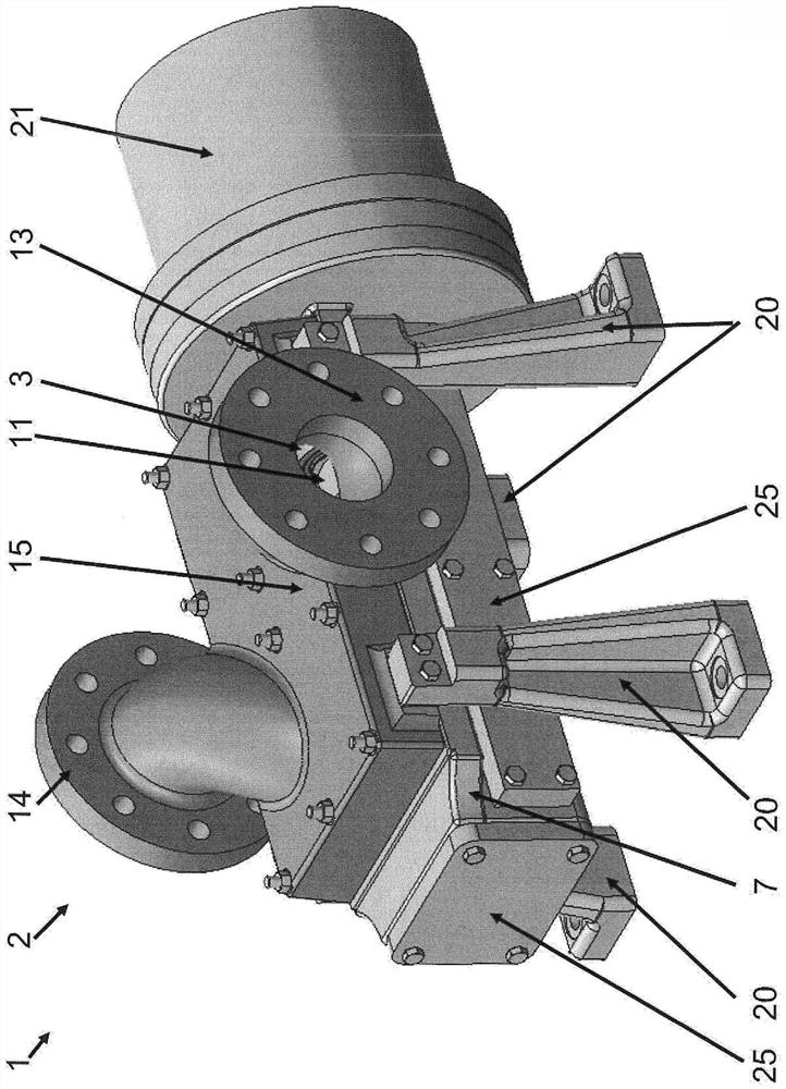
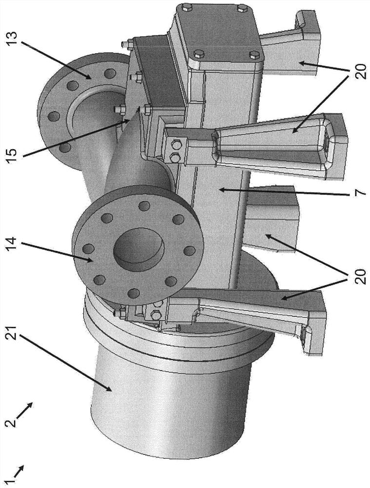
[0033] figure 1 A screw pump 1 is shown schematically, designated by reference numeral 1 . according to figure 1 The drawing shows a progressive cavity pump 1 comprising a multi-part housing 2 . The housing 2 comprises an operating housing part 7 and a connecting housing part 15 as well as a drive housing part 21 .
[0034]In addition to these housing parts 7 , 15 , 21 further housing parts may be provided for connection to said housing parts 7 , 15 , 21 . Thus, a discharge housing may be provided for assembly on the housing parts 7, 15, 21, wherein the discharge housing preferably comprises means to allow the screw pump 1 to be drained for maintenance. Furthermore, an attached housing including a flushing connection can be provided for inspection and cleaning of the progressive cavity pump 1 . It is also possible to use a pressure limiting valve housing and a bypass housing for assembly on the modular housing parts 7 , 15 , 21 of the progressive cavity pump 1 . Furthermo...
PUM
Abstract
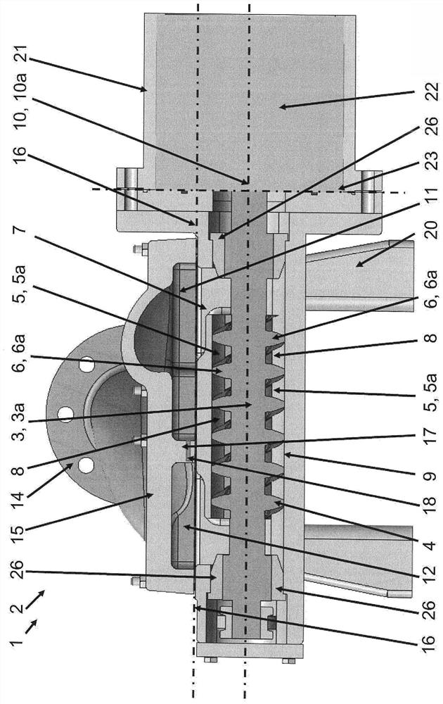
The invention relates to a screw pump (1), in particular a twin screw pump, comprising: a multi-part housing (2, 7, 15, 21) and at least two coupled chamber-forming rotors (3, 3a), each The rotors each comprise at least one thread-like profile (4, 4a) formed at least in regions and having a helical channel (5, 5a) and a dividing wall ( 6, 6a), wherein the rotors (3, 3a) perform reverse rotor rotations and the partition walls (6, 6a) mesh with each other in the manner of gears; and the running housing part (7), wherein the running housing part (7) surrounding the rotor (3, 3a) in a non-contact manner, wherein the rotor (3, 3a) together with the running housing part (7) forms at least one delivery chamber (8, 8a) for the fluid to be delivered, Among them, the transfer chamber (8, 8a) moves axially along the rotor shaft (10, 10a) and transfers the fluid from the suction chamber (11) to the pressure chamber (12); the suction side connection element (13), which is fluidly connected to a suction chamber (11); and a pressure-side connecting element (14), which is fluidly connected to the pressure chamber (12), wherein the suction-side connecting element (13) and the pressure-side connecting element (14) are arranged in the multi-part housing (2 , 7, 15, 21) on the connecting housing part (15), wherein the housing (2, 7, 15, 21) includes a planar dividing surface (16), which is in the running housing part ( 7) and the connecting housing part (15) extend parallel to the rotor shaft (10, 10a).
Description
technical field [0001] The present invention relates to a screw pump or screw shaft pump, in particular a single-flow or multi-flow twin screw pump or twin screw shaft pump, comprising: a multi-part housing and at least two coupled chamber-forming rotors, each rotor comprising at least one thread-like profile formed at least in regions and having a helical channel and a partition wall delimiting the channel, wherein the rotor performs a counter-rotor rotation and the partition walls mesh with each other in the manner of a gear; and a running housing body part, wherein the running housing part surrounds the rotor in a non-contact manner, wherein the rotor together with the running housing part forms at least one delivery chamber for the fluid to be delivered, wherein the delivery chamber is displaced axially along the rotor shaft, and A fluid is conveyed from the suction chamber to the pressure chamber; a suction side connection element is fluidly connected to the suction chamb...
Claims
Application Information
Patent Timeline
Application Date:The date an application was filed.
Publication Date:The date a patent or application was officially published.
First Publication Date:The earliest publication date of a patent with the same application number.
Issue Date:Publication date of the patent grant document.
PCT Entry Date:The Entry date of PCT National Phase.
Estimated Expiry Date:The statutory expiry date of a patent right according to the Patent Law, and it is the longest term of protection that the patent right can achieve without the termination of the patent right due to other reasons(Term extension factor has been taken into account ).
Invalid Date:Actual expiry date is based on effective date or publication date of legal transaction data of invalid patent.

