Compaction roller unit for spinning machine or twisting machine

A technology of pinching rollers and twisting machines, which can be used in spinning machines, spinning machines with continuous winding, textiles and papermaking, etc., and can solve problems such as slippage

Inactive Publication Date: 2017-08-11
SAURER GERMANY GMBH & CO KG
View PDF8 Cites 0 Cited by
  • Summary
  • Abstract
  • Description
  • Claims
  • Application Information

AI Technical Summary

Problems solved by technology

This can lead to different static frictions between the tangential drive belt and the spindle, whereby on the one hand slippage can occur if the static friction is too low and, on the other hand, undesired friction between the spindle and the tangential drive belt can occur if the static friction is too high. some fever

Method used


Image

  • Compaction roller unit for spinning machine or twisting machine
  • Compaction roller unit for spinning machine or twisting machine
  • Compaction roller unit for spinning machine or twisting machine

Examples


Embodiment Construction

[0025] In the following description of a preferred exemplary embodiment of the invention, the same or similar reference signs are used for similarly functioning components shown in the various figures, and a repeated description of these components is omitted here.

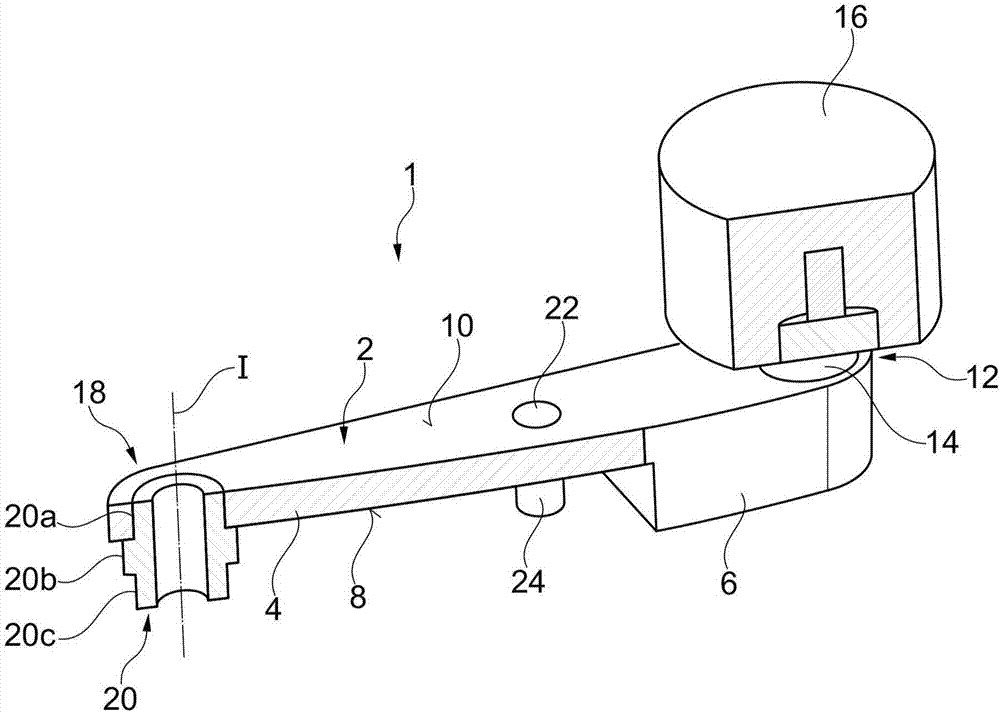
[0026] figure 1A partially cut-away perspective view of the pressure roller unit 1 according to one exemplary embodiment is shown. The pinch roller unit 1 comprises an elongated cantilever frame 2, the cantilever frame has a thin portion 4 in terms of cross-section and an adjacent thick portion 6 in terms of cross-section in the direction of longitudinal extension, the thickness of the thick portion is The section is formed thicker than the thin section 4 . The thin section 4 transitions to the thick section 6 on the first surface side 8 of the boom 2 via a stepped structure. On the second surface side 10 of the cantilever frame 2 facing away from the first surface side 8 , the thin portion 4 and the thick porti...


PUM


Abstract

The invention discloses a compaction roller unit for a spinning machine or a twisting machine. The compaction unit applies a spring elastic pressure on a conveying belt (48) of the spinning machine or the twisting machine. The compaction roller unit (1) includes a compaction roller (16) which is rotatably retained at a first bearing point (12) by a cantilever support (2). The cantilever support (2) has a second bearing point (18). The second bearing point and the first bearing point (12) are spaced apart, and the cantilever support (2) can be retained on the spinning machine or the twisting machine as the second bearing point may rotate around a rotating axis (I) so as to move the compaction roller (16) to move in the direction of the conveying belt (48). According to the invention, the compaction roller unit is characterized in that the cantilever support (2) is formed in the rotating direction in an anti-bending manner and has a spring piece system (24) which actions in the rotating direction and can bear a spring piece (26) which can be effectively connected to the cantilever support (2;2') in a manner for transmitting the spring force, wherein the spring piece system (24) is arranged on one side of the second bearing point (18) facing the compaction roller (16).

Description

technical field [0001] The invention relates to a pressure roller unit for applying spring elastic pressure to a drive belt of a spinning or twisting machine. Background technique [0002] Spinning or twisting machines generally comprise at least one spindle rail with a plurality of spindles driven via a common drive belt, wherein the drive belt is driven by a drive connected to the spindle rail. The drive belt is a so-called tangential drive belt, which is circulated on the spindle rail in static friction contact with several spindles by deflection rollers and tangential drive pulleys, which are driven in rotation by a drive device in a defined manner, whereby the drive belt is driven. The tangential drive belt is pressed spring-loaded against the two spindles for the respective static friction drive by means of pressure rollers arranged between the two adjacent spindles. The pinch rollers are combined in pairs to form a pinch roll hanger that is fixed on the spindle rail....

Claims


Application Information

Patent Timeline
Patent Type & Authority Applications(China)
IPC IPC(8): D01H1/241
CPCD01H1/241
Inventor 彼得·曼恩
Owner SAURER GERMANY GMBH & CO KG
Why Eureka
Try Eureka