Wiring piece, block terminal and method for cutting wire

A technology of lugs and distribution boxes, applied in the direction of connecting/terminating cables, electrical components, transportation and packaging, etc., can solve problems such as inability to form circuits, inability to efficiently perform cutting wires 507, etc.

Inactive Publication Date: 2004-04-14
YAZAKI CORP
View PDF0 Cites 6 Cited by
  • Summary
  • Abstract
  • Description
  • Claims
  • Application Information

AI Technical Summary

Problems solved by technology

[0007] However, in the related power distribution box 501 described above, the electric wires 507 mounted on the terminal block 504 need to be cut one by one using tools such as pliers (not shown), so the operation of cutting the electric wires 507 cannot be efficiently performed.
In addition, if the worker forgets to cut one or more wires 507, the intended circuit cannot be formed

Method used


Image

  • Wiring piece, block terminal and method for cutting wire
  • Wiring piece, block terminal and method for cutting wire
  • Wiring piece, block terminal and method for cutting wire

Examples


Embodiment Construction

[0059] Hereinafter, a lug, a distribution box, and a wire cutting method embodying the present invention will be described in detail with reference to the accompanying drawings.

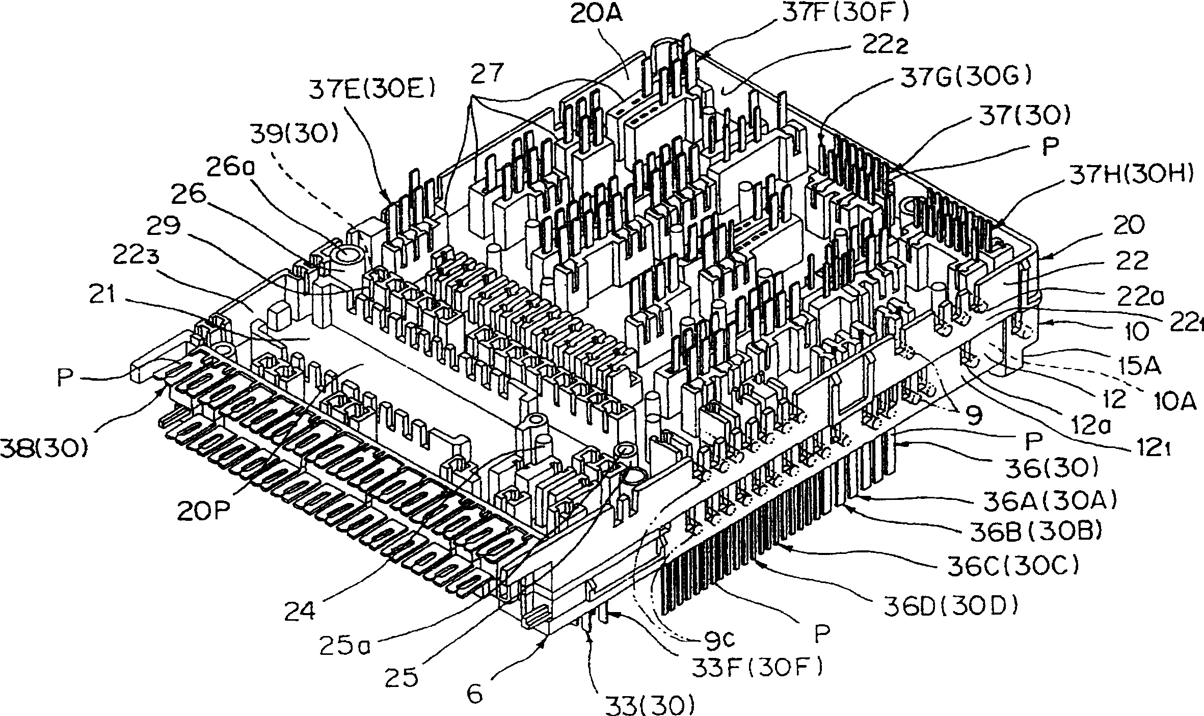
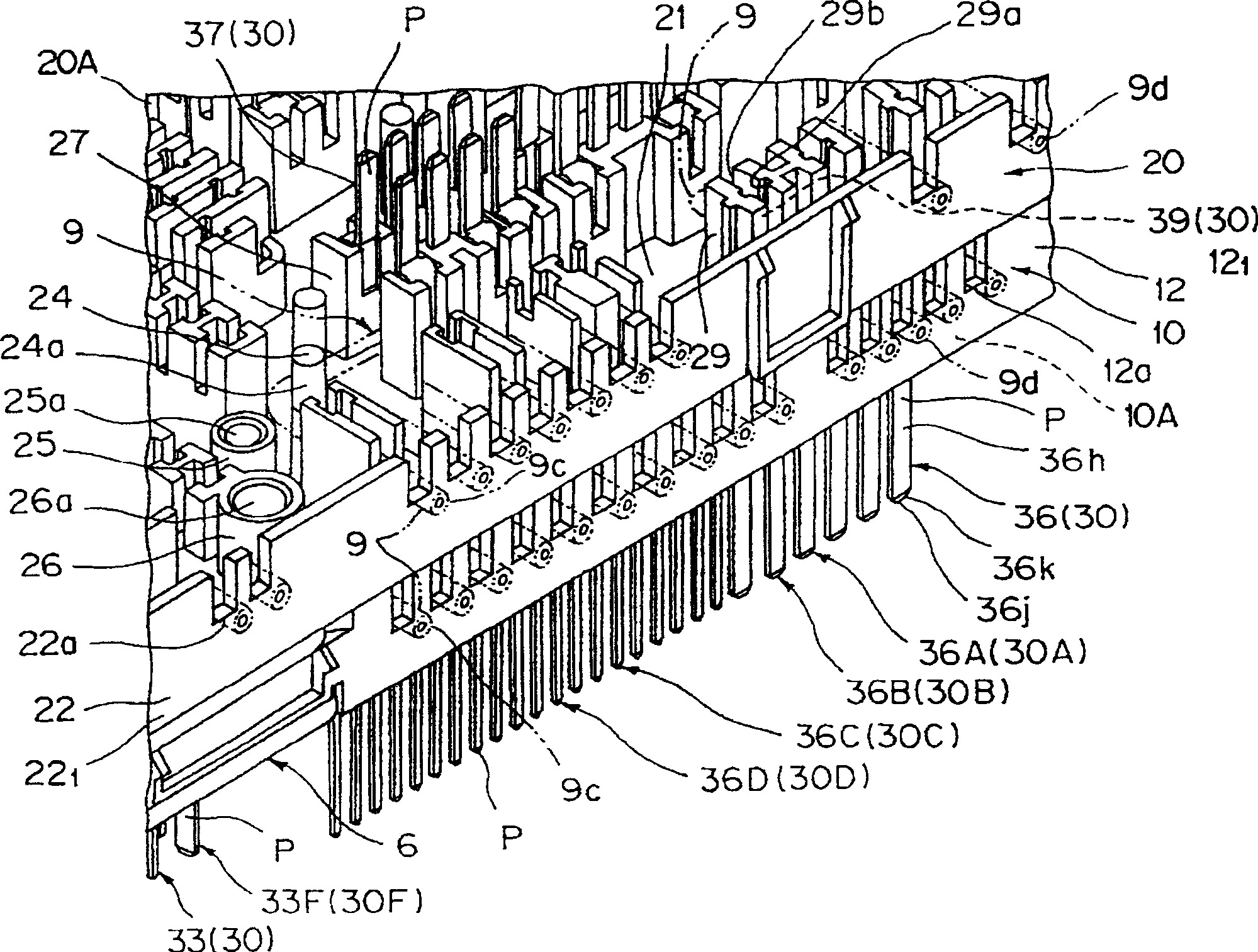
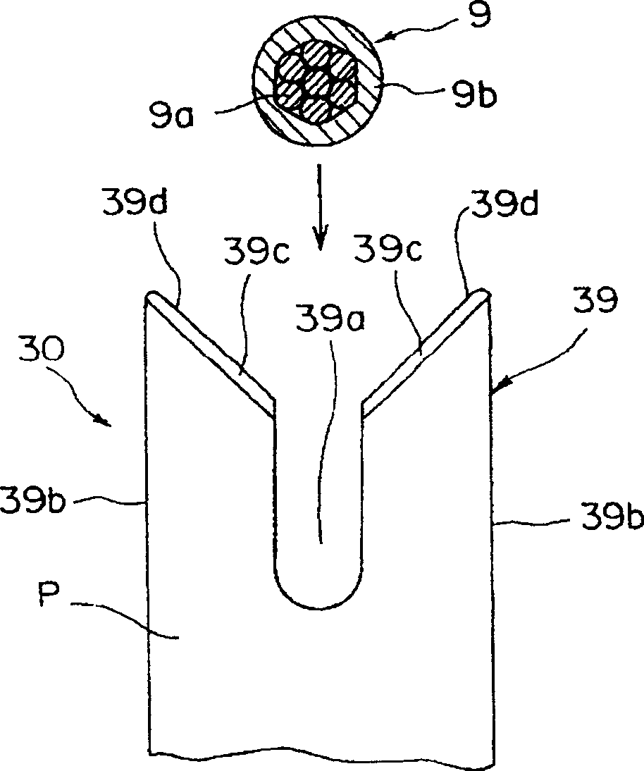
[0060] Figure 1 to Figure 9 A preferred embodiment of the present invention is shown, showing lugs, distribution boxes and wire cutting methods.

[0061] Referring to the upper and lower sides of lugs 10 and 20, as figure 1 and figure 2 As shown, the side on which the electrical contact portion 37 of the bus bar 30 protrudes from the lug 20 is the lower side. figure 1 and figure 2 The underside of lug 20 is shown. The side where the electrical contact portion 36 of the bus bar 30 protrudes from the lug 10 is the upper side, as figure 1 , 2 , 4 and 5.

[0062] Refer to attached Figure 6 For different directions of the distribution box 1, the side where the electronic unit 5 is disposed in the distribution box 70 is the upper side, and an example where the synthetic resin supporting memb...


PUM


Abstract

A wiring sheet for installing a plurality of wires thereon includes a side plate portion, at which end portions of the wires forming circuits are collectively disposed.

Description

technical field [0001] The present invention relates to a lug and a power distribution box in which, for example, an electronic unit (electronic control unit) for a vehicle is installed and a wire cutting operation can be easily performed, and a method of cutting a wire. Background technique [0002] Figure 13 A related distribution box is shown. [0003] The distribution box 5041 includes: an upper cover 502 made of synthetic resin; a lower cover 503 (i.e. the distribution box body); Bus bar terminal block 505 . [0004] The wire terminal board 504 includes: an insulating plate portion 506 made of synthetic resin; a plurality of insulating sheathed electric wires 507 arranged on the surface of the insulating plate portion 506; contact terminal 508. A crimped contact portion 508a is formed at one end of the terminal 508, and a raised strip-shaped electrical contact portion 508b is formed at the other end thereof. [0005] The bus bar terminal board 505 includes: an insu...

Claims


Application Information

Patent Timeline
Patent Type & Authority Applications(China)
IPC IPC(8): H02G3/16B60R16/02B60R16/023
CPCB60R16/0238
Inventor 原康宏
Owner YAZAKI CORP
Why Eureka
Try Eureka