A multifunctional valve and its combination valve

A multi-functional valve and combined valve technology, applied in the direction of multi-way valves, valve details, valve devices, etc., can solve the problem that cylinder pistons cannot work well in sequence, piston and cylinder end cover wear, piston and cylinder end Cover damage and other problems, to achieve the effect of reasonable and practical structure, avoid collision wear and increase resistance

Inactive Publication Date: 2015-12-16
靖江市华信科技创业园有限公司
View PDF7 Cites 0 Cited by
  • Summary
  • Abstract
  • Description
  • Claims
  • Application Information

AI Technical Summary

Problems solved by technology

Not only can it produce a lot of collision noise, but it will inevitably cause serious wear to the piston and cylinder end cover
After being used for a period of time, it will inevitably cause certain damage to the piston and the end cover of the cylinder body; the higher the pressure, the faster the speed, and the shorter the service life of the piston cylinder
[0003] Although the inventor disclosed an improved combination valve in the document of a multi-function valve and its combination valve in 201110398070.3 to prevent the piston from impacting the cylinder end cover, thereby prolonging the service life of the piston cylinder, in practice It shows that there are still some deficiencies in some applications. For example, the working time sequence of the two cylinders is different, which will cause the fluid pressure in one cylinder to affect the fluid pressure in the other cylinder, which is to produce certain mutual interference. As a result, the cylinder pistons controlled by each reversing control valve cannot work well in sequence, and further improvement is required

Method used


Image

  • A multifunctional valve and its combination valve
  • A multifunctional valve and its combination valve
  • A multifunctional valve and its combination valve

Examples


Embodiment 1

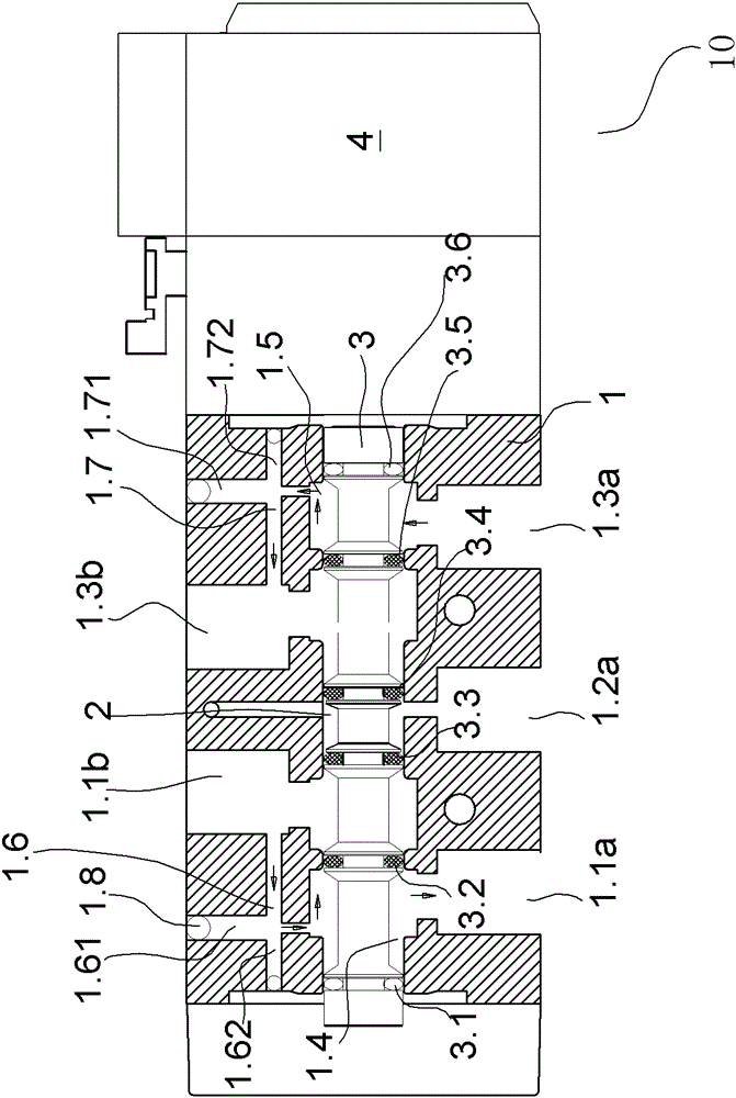
[0051] like figure 1 As shown, the multifunctional valve 10 includes a valve body 1 with a valve cavity 2 inside the valve body, and a valve stem 3 installed in the valve cavity 2, the valve stem 3 adopts an integral structure, so the valve body 1 is provided with a The middle inlet 1.2a for the pressure medium to enter, the left inlet 1.1a and the right inlet 1.3a for the pressure medium to enter selectively, and the other side of the valve body 1 is provided with the left outlet 1.1b and the right outlet 1.3b for the pressure medium to discharge. The left inlet 1.1a communicates with the left sub-chamber 1.4 in the valve chamber 2, the right inlet 1.3a communicates with the right sub-chamber 1.5 in the valve chamber 2, the left sub-cavity 1.4 communicates with the left outlet 1.1b through the damping channel 1.6, and the right sub-cavity The cavity 1.5 communicates with the right outlet 1.3b through the damping channel 1.7.

[0052] The damping channel 1.6 is formed by conn...

Embodiment 2

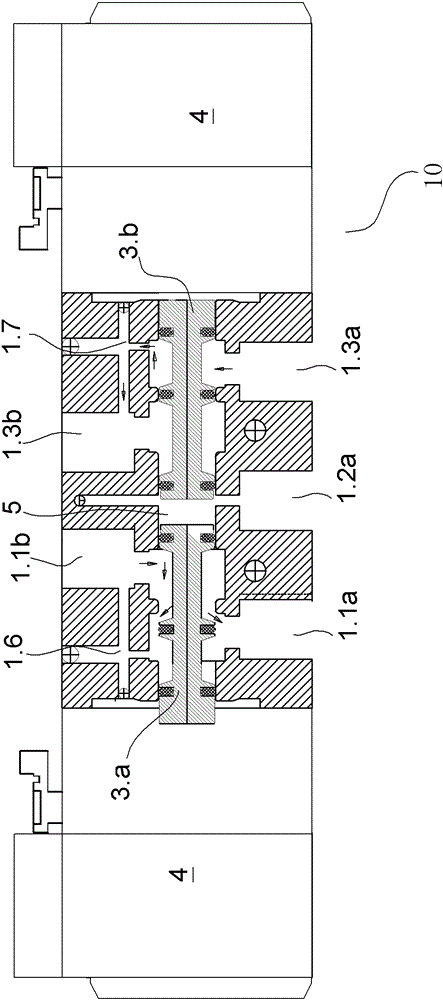
[0058] like figure 2 As shown, in the present implementation example, the valve stem 3 is divided into the left valve stem 3.a, the right valve stem 3.b, the gap cavity 5 and the pressure medium entering between the left valve stem 3.a and the right valve stem 3.b The middle inlet 1.2a is connected, and the ends of the left and right valve stems are respectively connected to their respective solenoid valves 4, so that the left inlet and the left outlet or the right inlet and the right outlet cannot be connected directly, but are connected through damping flow channels. , and others are similar to the implementation example 1.

Embodiment 3

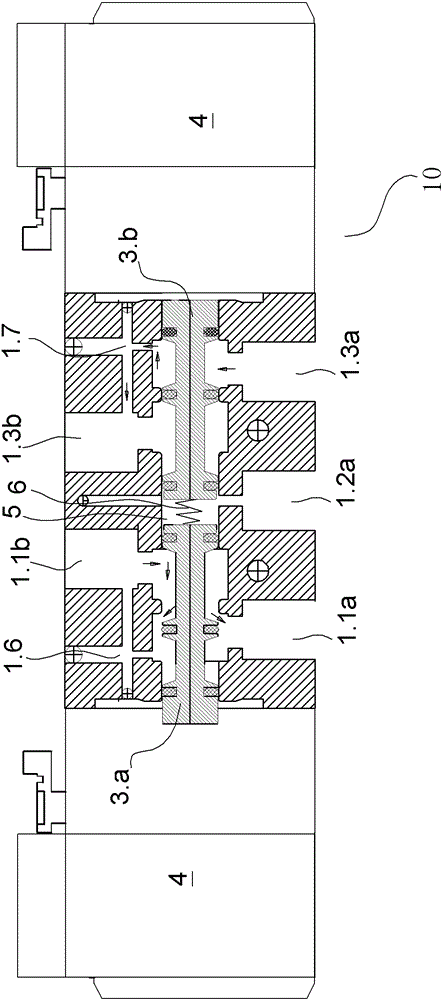
[0060] like image 3 As shown, in the present implementation example, the valve stem 3 is divided into the left valve stem 3.a, the right valve stem 3.b, the gap cavity 5 and the pressure medium entering between the left valve stem 3.a and the right valve stem 3.b The middle inlet 1.2a is connected, and the left and right valve stems are also provided with an elastic member 6 for the back movement of the left and right valve stems. Either the left inlet and the left outlet or the right inlet and the right outlet cannot be connected directly, but are connected through a damping flow channel, and the others are similar to the implementation example 1.


PUM


Abstract

The invention relates to a multifunctional valve and a combination valve thereof. The multifunctional valve comprises a valve body, a valve cavity formed in the valve body and a valve rod arranged in the valve cavity, wherein a middle inlet allowing pressure media to enter, a left inlet and a right inlet are formed in one surface of the valve body, and the pressure media can selectively enter the left inlet and the right inlet; a left outlet and a right outlet which allow the pressure media to be discharged are formed in the other surface of the valve body; and the left inlet and the left outlet as well as the right inlet and the right outlet are selectively and correspondingly communicated through matching of the valve cavity and the valve rod. The multifunctional valve is characterized in that the left inlet and the right inlet are communicated with the left outlet and the right outlet through respective damping channels, so that a piston can slowly touch the end part of a piston cylinder, a piston rod is prevented from being collided and abraded when the piston moves at a high speed, the service life of the piston cylinder is effectively prolonged, and simultaneously, operation safety and stability of the piston cylinder are guaranteed.

Description

technical field [0001] The invention relates to the technical field of buffer valves and related valve groups. Background technique [0002] When the piston cylinder works at high speed or high pressure, the movement speed of the piston rod and the piston is very fast. In this way, when the piston quickly moves to the two limit positions of the front end and the rear end of the cylinder body, the piston and the end cover of the cylinder body will inevitably be closed. Collision. Not only can it produce a lot of collision noise, but it will inevitably cause serious wear and tear on the piston and the end cover of the cylinder block. After using for a period of time, it will inevitably cause certain damage to the piston and the end cover of the cylinder body; the higher the pressure, the faster the speed, and the shorter the service life of the piston cylinder. [0003] Although the inventor disclosed an improved combination valve in the document of a multi-function valve an...

Claims


Application Information

Patent Timeline
Patent Type & Authority Patents(China)
IPC IPC(8): F16K11/07F16K27/04F16K31/122
Inventor 皇甫岳伟
Owner 靖江市华信科技创业园有限公司
Why Eureka
Try Eureka