Supercharge Your Innovation With Domain-Expert AI Agents!

Protective nozzle cap, plasma arc torch comprising said protective nozzle cap, and use of the plasma arc torch

A plasma and protective cover technology, applied in the direction of plasma, electrical components, etc., can solve the problems of degradation of cutting quality, damage of nozzle protective cover, etc.

Inactive Publication Date: 2019-07-19
КЬЕЛЛЬБЕРГ-ШТИФТУНГ
View PDF13 Cites 1 Cited by
  • Summary
  • Abstract
  • Description
  • Claims
  • Application Information

AI Technical Summary

Problems solved by technology

This can lead to damage to the nozzle protection cap and also to a deterioration of the cut quality due to disruption of the flow of the secondary gas

Method used


Image

  • Protective nozzle cap, plasma arc torch comprising said protective nozzle cap, and use of the plasma arc torch
  • Protective nozzle cap, plasma arc torch comprising said protective nozzle cap, and use of the plasma arc torch

Examples


Embodiment Construction

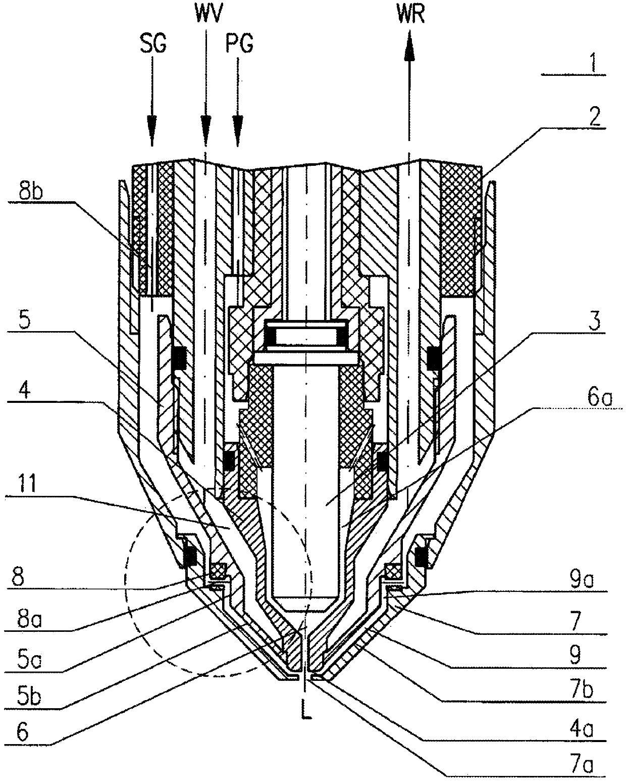
[0033] figure 1 A plasma torch 1 according to a particular embodiment of the invention is shown. The plasma torch 1 has a torch body 2 and an electrode 3 and a nozzle 4 which are substantially rotationally symmetrical about a longitudinal axis L of the plasma torch 1 . The electrode 3 and the nozzle 4 coaxially arranged in the torch body 2 are positioned in a specific spatial relationship and form a plasma chamber 6 through which a plasma gas PG flows, which is supplied through a plasma gas channel 6a. The nozzle cover 5 is arranged coaxially with respect to the longitudinal axis L of the plasma torch 1 and holds and surrounds the nozzle 4 with a protective effect. The cavity 11 through which the cooling water flows is located between the nozzle 4 and the nozzle cover 5 . Cooling water is supplied through the water supply channel WV and flows out through the water return channel WR.

[0034] An annular secondary gas guide portion 8 having a plurality of passages (particular...


PUM

PropertyMeasurementUnit
thermal conductivityaaaaaaaaaa
hardnessaaaaaaaaaa

Abstract

The protective nozzle cap (7) of the invention for a plasma arc torch (1) is positioned and secured externally on the tip of the plasma arc torch (1) at which a plasma jet exits the plasma arc torch (1) through nozzle-type openings (4a, 7a). The protective nozzle cap (7) is made of an iron alloy containing at least 0.05% sulfur.

Description

technical field [0001] The invention relates to a nozzle protection cover for a plasma arc torch, a plasma arc torch with the nozzle protection cover, and uses of the plasma arc torch. Background technique [0002] Plasma arc torches can be used both for dry cutting and are particularly advantageous for underwater cutting of various metal workpieces. [0003] In the case of plasma cutting, an electric arc is first ignited (piloted arc) between the cathode (electrode) and anode (nozzle) and then transferred directly to the workpiece in order to cut there. [0004] The arc forms a plasma, which is a high-temperature heated conductive gas (plasma gas) composed of positive and negative ions, electrons, and excited neutral atoms and molecules. A gas such as argon, hydrogen, nitrogen, oxygen or air is used as the plasma gas. These gases are ionized and dissociated by the energy of the arc. The resulting plasma jet is used to cut the workpiece. [0005] A modern plasma arc torc...

Claims


Application Information

Patent Timeline
Patent Type & Authority Applications(China)
IPC IPC(8): H05H1/34
CPCH05H1/34H05H1/3457H05H1/28
Inventor 延斯·弗里德尔蒂莫·格伦德克沃克·克林克
Owner КЬЕЛЛЬБЕРГ-ШТИФТУНГ
Features
  • R&D
  • Intellectual Property
  • Life Sciences
  • Materials
  • Tech Scout
  • Unparalleled Data Quality
  • Higher Quality Content
  • 60% Fewer Hallucinations
Learn More