Plasma-jet spark plug and ignition system

a technology of spark plugs and plasma jets, which is applied in the direction of spark plugs, instruments, machines/engines, etc., can solve the problems of deterioration of electrode durability, adverse influences, and increase of plasma ejection length, so as to achieve maximum ignition performance and improve ignitability

Inactive Publication Date: 2007-09-27
NGK SPARK PLUG CO LTD
View PDF4 Cites 34 Cited by
  • Summary
  • Abstract
  • Description
  • Claims
  • Application Information

AI Technical Summary

Benefits of technology

[0007]It is therefore an object of the present invention to provide a plasma-jet spark plug capable of ejecting a plasma from a discharge cavity through a ground electrode opening in such a manner as to maximize ignition performance and obtain improvement in ignitability.

Problems solved by technology

The increase of the plasma ejection length does not, however, always contribute to ignition improvement.
Further, some of the configuration modifications of the discharge cavity can cause adverse influences such as deteriorations in electrode durability.

Method used


Image

  • Plasma-jet spark plug and ignition system
  • Plasma-jet spark plug and ignition system
  • Plasma-jet spark plug and ignition system

Examples


experiment 1

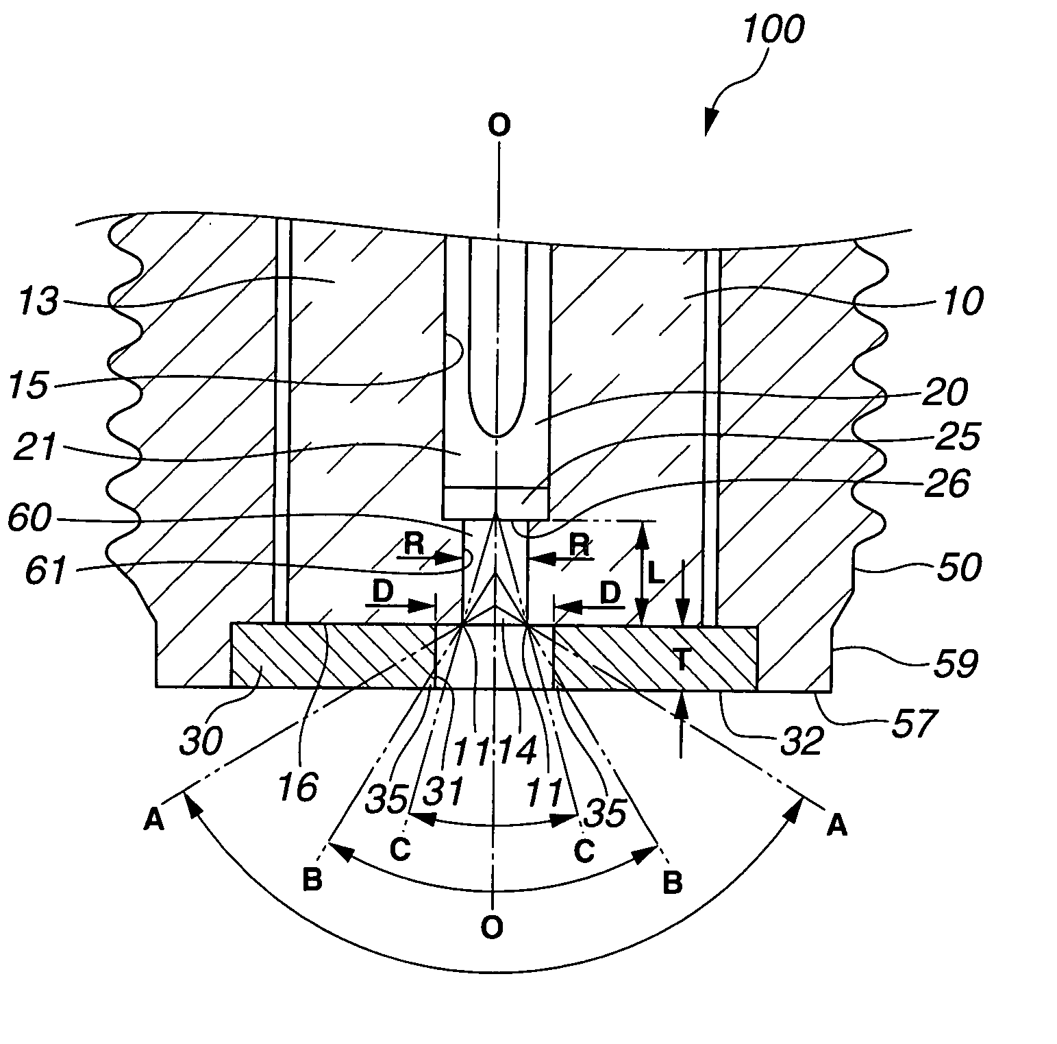
[0054]A test sample of the spark plug 100 was produced with the following dimensions: D=1.0 mm, T=1.0 mm, R=0.5 mm and L=2.0 mm where D was the minimum diameter of the opening 31 of the ground electrode 30; T was the axial thickness of the ground electrode 30; R was the diameter of the discharge cavity 60 (the diameter of the insulator opening 14 at the front opening edge 11); and L was the depth of the discharge cavity 60 (the distance between the front end face 16 of the ceramic insulator 10 and the front end face 26 of the center electrode 20 along the plug axis direction). The test sample was then subjected to ignitability test. The ignitability test was conducted by mounting the test sample in a pressure chamber, charging the chamber with a mixture of air and C3H8 fuel gas (air-fuel ratio: 22) to a pressure of 0.05 MPa, activating the test sample by means of a CDI-circuit power source and monitoring the pressure in the chamber with a pressure sensor to judge the success or fail...

experiment 2

[0055]Test samples of the spark plug 100 were produced in the same manner as in Experiment 1 and subjected to durability test. In each of the test samples, the ground electrode 30 was made of Ir-5Pt alloy. The durability test was conducted by charging a pressure chamber with N2 gas to a pressure of 0.4 MPa, mounting the test sample in the pressure chamber, activating the test sample by means of a CDI-circuit power source to cause a continuous discharge at 60 Hz for 200 hours and measuring the amount of consumption of the ground electrode 30 during the continuous discharge. The output of the power source was varied from sample to sample. The test results are indicated in FIG. 7. The test sample had an electrode consumption of about 0.06 mm3 by the energy supply of 100 mJ. The test sample had an electrode consumption of about 0.08 mm3 by the energy supply of 150 mJ. Further, the test sample had an electrode consumption of slightly less than 0.10 mm3 by the energy supply of 200 mJ. The...

experiment 3

[0056]Three test samples of the spark plug 100 were produced with the following dimensions: T=1.0 mm, R=0.5 mm and L=2.0 mm. In these three test samples, the opening 31 of the ground electrode 30 was formed in such a manner that the opening defining portion of the ground electrode 30 was in contact with an imaginary circular surface line having a vertex angle of 110°, 115° and 120°. A test sample of comparative spark plug was produced under the same conditions as above except that the opening defining portion of the ground electrode was in contact with an imaginary circular conical surface line having a vertex angle of 125°. Each of the test samples was then subjected to discharge test. The discharge test was conducted by charging a pressure chamber with N2 gas to a pressure of 0.4 MPa, mounting the test sample in the pressure chamber and activating the test sample by means of a power source of 140-mJ capacity to measure a discharge voltage required for the test sample to cause a co...


PUM


Abstract

A plasma-jet spark plug includes a metal shell, an electrical insulator retained in the metal shell, a center electrode held in an axial hole of the electrical insulator to define a cavity by a front end face of the center electrode and an inner circumferential surface of the insulator axial hole and a ground electrode arranged on a front end of the electrical insulator. The ground electrode has an opening defining portion defining an opening for communication between the cavity and the outside of the spark plug. The opening defining portion is located radially inside of or in contact with a first imaginary circular conical surface where the first imaginary circular conical surface has an axis coinciding with an axis of the spark plug and a vertex angle of 120° opening toward a front end of the spark plug and passing through a front edge of the insulator axial hole.

Description

BACKGROUND OF THE INVENTION[0001]The present invention relates to a plasma-jet spark plug that produces a plasma by a spark discharge to ignite an air-fuel mixture in an internal combustion engine. The present invention also relates to an ignition system using the plasma-jet spark plug.[0002]A spark plug is widely used in an automotive internal combustion engine to ignite an air-fuel mixture by a spark discharge. In response to the recent demand for high engine output and fuel efficiency, it is desired that the spark plug increase in ignitability to show a higher ignition-limit air-fuel ratio and achieve proper lean mixture ignition and quick combustion.[0003]One example of high-ignitability spark plug is known as a plasma-jet spark plug. The plasma-jet spark plug has a pair of center and ground electrodes defining therebetween a discharge gap and an electrical insulator surrounding the discharge gap so as to form a discharge cavity within the discharge gap. In the plasma-jet spark ...

Claims


Application Information

Patent Timeline
Patent Type & Authority Applications(United States)
IPC IPC(8): F02B19/00H01T13/20F02P23/00
CPCF02P9/007H01T13/52H01T13/50
Inventor HAGIWARA, KATSUNORINAGASAWA, SATOSHIMATUTANI, WATARUNAKAMURA, TORUKATO, TOMOAKIYAMADA, YUICHI
Owner NGK SPARK PLUG CO LTD
Why Eureka
Try Eureka