Internal combustion engine and control device for the internal combustion engine

a control device and internal combustion engine technology, applied in the direction of electric control, machines/engines, output power, etc., can solve the problems of deterioration in thermal efficiency, ignitability and limitations in the leaning of air fuel mixture, affecting the ignitability of the fuel mixture, etc., to achieve the effect of improving ignitability and improving ignitability

Active Publication Date: 2006-05-30
TOYOTA IND CORP
View PDF17 Cites 31 Cited by
  • Summary
  • Abstract
  • Description
  • Claims
  • Application Information

AI Technical Summary

Benefits of technology

[0007]The present invention has been made in view of the above problems in the prior art. It is an object of the present invention to provide, from the viewpoint of enhancement in thermal efficiency and a reduction in NOx, an internal combustion engine and an internal combustion engine control device in which an improvement in terms of ignitability is achieved even with a fuel hard to ignite and in which an improvement in terms of thermal efficiency is achieved, making it possible to enlarge the load range allowing operation.

Problems solved by technology

However, in the case of a gasoline engine, in which spark ignition is effected from the viewpoint of controlling the ignition timing, the flame core formation by ignition and flame propagation are rather difficult to perform, which leads to a problem in ignitability and limitations in the leaning of the air fuel mixture.
As in the case of a gasoline engine, in the case of a gas engine using natural gas, propane gas or the like, ignition is rather difficult to effect, resulting in a problem similar to that in a gasoline engine.
However, it is liable to generate soot, and involves a problem regarding NOx discharge.
However, when the amount of residual gas trapped increases, the heat loss and pump loss due to the compression and expansion of the gas increase, resulting in a deterioration in thermal efficiency.
Further, since the intake amount of the newly sucked gas decreases, the load range allowing operation is restricted.

Method used


Image

  • Internal combustion engine and control device for the internal combustion engine
  • Internal combustion engine and control device for the internal combustion engine
  • Internal combustion engine and control device for the internal combustion engine

Examples


Embodiment Construction

[0045]Preferred embodiments of the present invention will now be described with reference to the drawings.

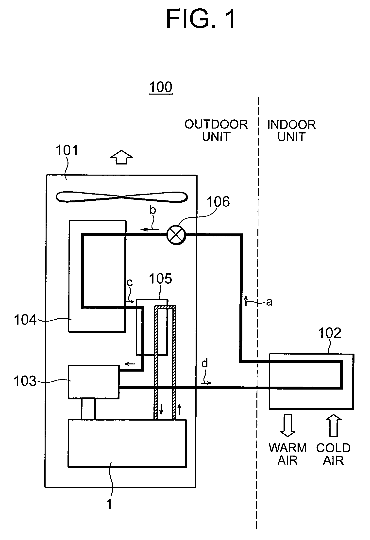
[0046]FIG. 1 is a system diagram showing an example of a gas heat pump equipped with an internal combustion engine. An internal combustion engine according to the present invention can be used, for example, in a gas heat pump 100 shown in FIG. 1. In this gas heat pump 100, a heat pump cycle is driven by an internal combustion engine (gas engine) using natural gas or the like to effect air conditioning. The system example shown in FIG. 1 functions as a space-heating cycle.

[0047]The gas heat pump 100 is equipped with an outdoor unit 101 and an indoor unit 102. The outdoor unit 101 is equipped with an internal combustion engine (gas engine) 1 according to this embodiment, a compressor 103 driven by the internal combustion engine 1, heat exchangers 104 and 105, an expansion valve 106, etc. Refrigerant is condensed by the heat exchanger on the indoor unit 102 side and liquefied to th...


PUM


Abstract

Disclosed is an internal combustion engine in which it is possible to provide, from the exhaust stroke to the intake stroke, a period T during which both an intake valve (14) and an exhaust valve (15) remain closed, the internal combustion engine being equipped with a fuel injection valve (24) capable of injecting fuel into a combustion chamber (16), the closing time EVC for the exhaust valve (15) being set to be on the advance side with respect to the intake top dead center, the fuel injected from the fuel injection valve (24) being pressurized together with a residual gas inside the combustion chamber (16) during the period T in which both the intake valve (14) and the exhaust valve (15) remain closed.

Description

BACKGROUND OF THE INVENTION[0001]1. Field of the Invention[0002]The present invention relates to an internal combustion engine in which it is possible to set a period during which both an intake valve and an exhaust valve are closed from an exhaust stroke to an intake stroke.[0003]2. Description of the Related Art[0004]As is well known in the art, generally speaking, in a four-cycle internal combustion engine, an improvement in theoretical thermal efficiency is achieved through an increase in the ratio of specific heat of a working fluid by making an air fuel mixture lean. However, in the case of a gasoline engine, in which spark ignition is effected from the viewpoint of controlling the ignition timing, the flame core formation by ignition and flame propagation are rather difficult to perform, which leads to a problem in ignitability and limitations in the leaning of the air fuel mixture. As in the case of a gasoline engine, in the case of a gas engine using natural gas, propane ga...

Claims


Application Information

Patent Timeline
Patent Type & Authority Patents(United States)
IPC IPC(8): F02B47/08F02M21/00B60T7/12F01L13/00F02B1/12F02B3/10F02B7/02F02B7/06F02B11/00F02D13/02F02D19/02F02D41/30F02D41/40F02D43/00F02M21/02F02M63/00
CPCF02D13/0207F02D13/0215F02D13/0265F02D41/3094F02D41/401F02D41/3035F02B1/12F02D41/006Y02T10/18F02D2041/001F02D2041/389Y02T10/44F02D41/402Y02T10/12Y02T10/40
Inventor KUZUYAMA, HIROSHIKAWAI, KENJI
Owner TOYOTA IND CORP
Why Eureka
Try Eureka