Plasma-jet spark plug and ignition system
a technology of spark plugs and spark plugs, applied in spark plugs, instruments, machines/engines, etc., can solve problems such as deterioration of durability of spark plugs
- Summary
- Abstract
- Description
- Claims
- Application Information
AI Technical Summary
Benefits of technology
Problems solved by technology
Method used
Image
Examples
experiment 1
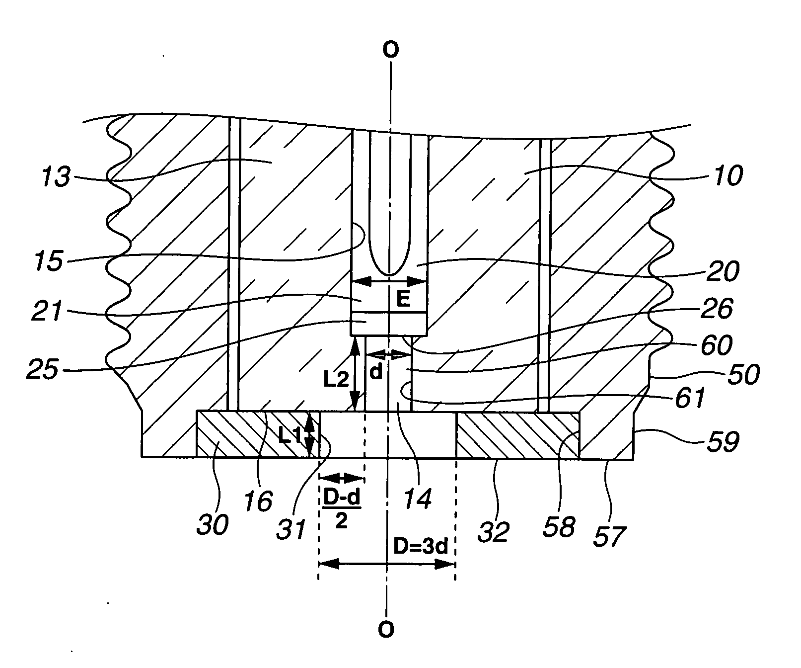
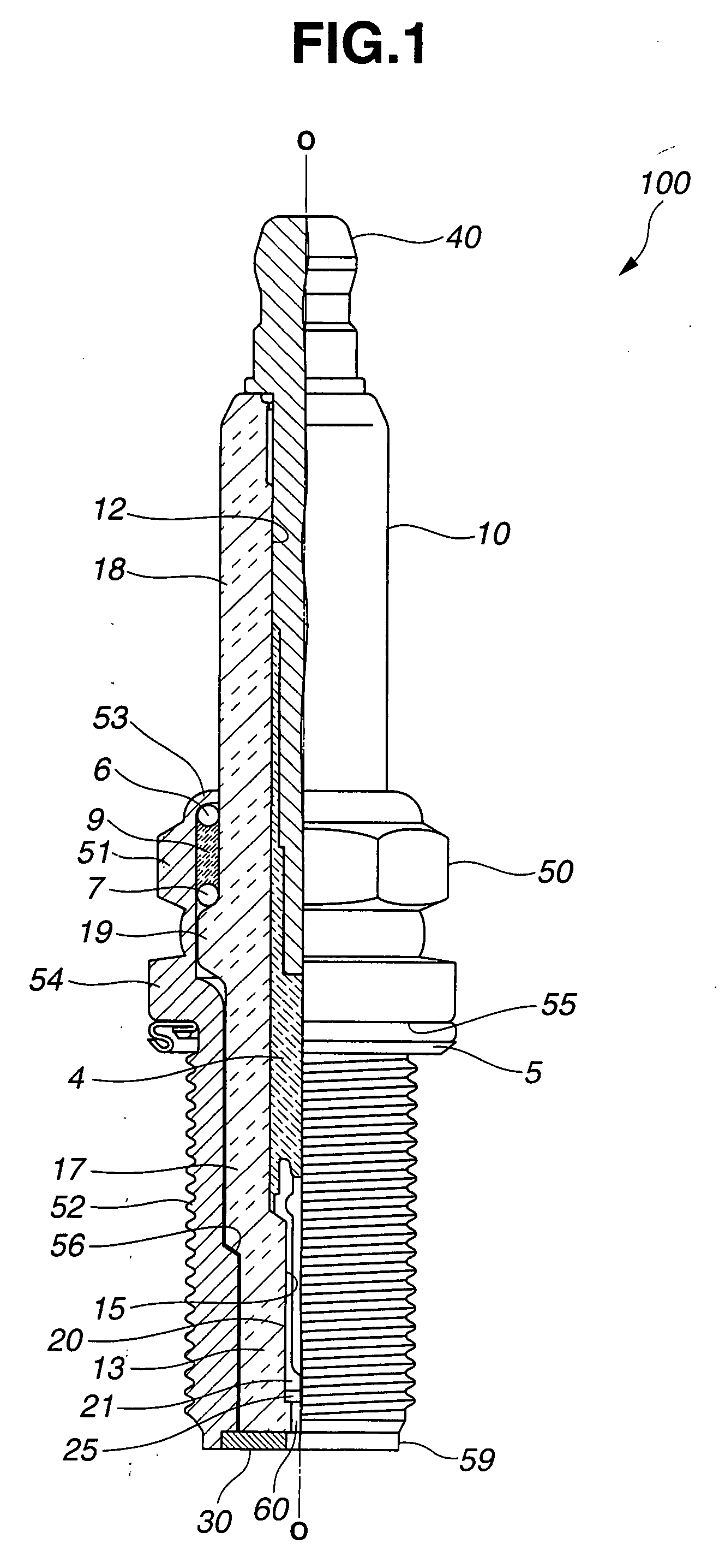
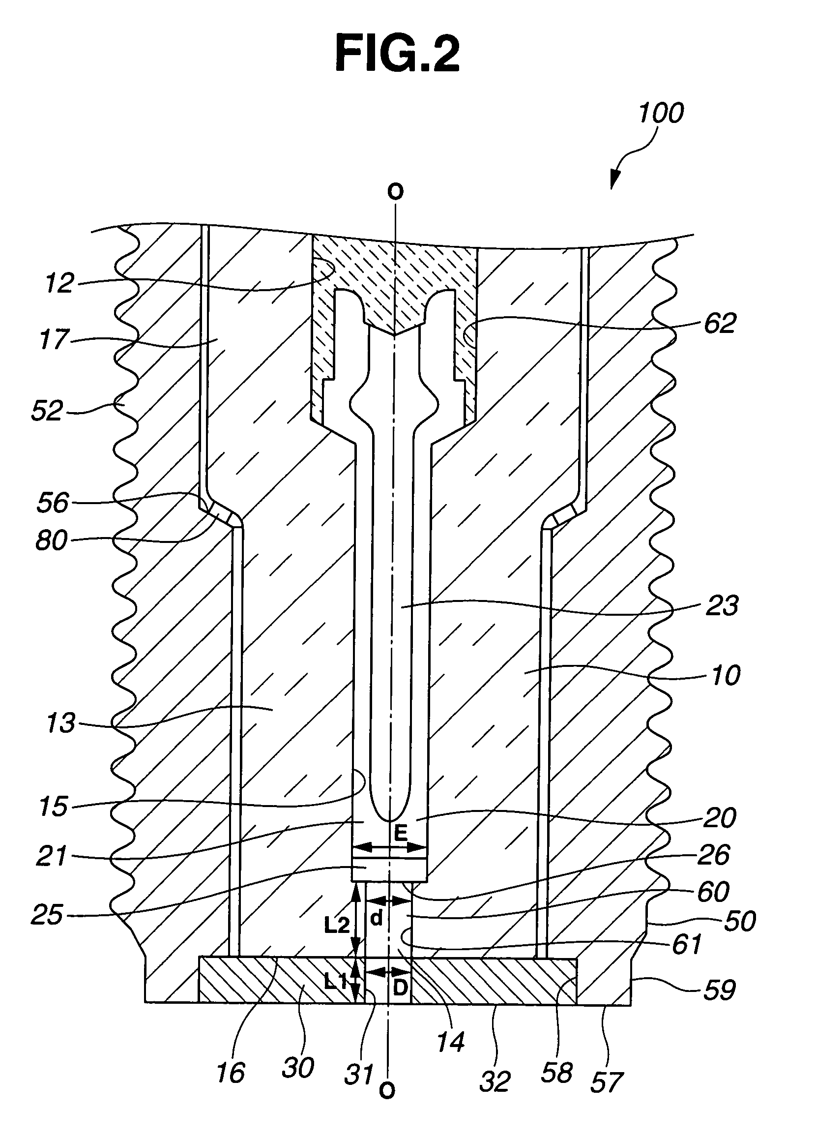
[0041]Test samples (sample numbers 1-1 and 1-2) of the spark plug 100 and test samples (sample numbers 1-3 and 1-4) of comparative spark plugs were produced under the same conditions except for their dimensions. The dimensions of the test samples are indicated in TABLE 1. Using the power supply unit 200 having a capacity to supply 200 mJ of energy for one discharge shot, each of the test samples was activated to eject a plasma. The length of the plasma ejected from the front end face 32 of the ground electrode 30 was determined by image observation. The test sample was judged to have succeeded in plasma flame discharge and rated as “◯” when the plasma ejection length was 2 mm or larger. When the plasma ejection length was smaller than 2 mm, the test sample was judged to have failed in plasma flame discharge and rated as “X”. The test results are indicated in TABLE 1.
TABLE 1PlasmaSampleDL1dL2L1 + L2flameNo.(mm)(mm)(mm)(mm)(mm)discharge1-10.80.80.81.72.5d = D◯1-20.81.50.83.55.0d = D◯1...
experiment 2
[0042]Test samples (sample numbers 2-1 and 2-2) of the spark plug 100 and test sample (sample number 2-3) of comparative sample plug were produced under the same conditions except for their dimensions. The dimensions of the test samples are indicated in TABLE 2. Using the power supply unit 200 having a capacity to supply 160 mJ of energy for one discharge shot, each of the test samples was activated to eject a plasma. The ejection length of the plasma was determined by image observation to judge whether the test sample succeeded or failed in plasma flame discharge in the same manner as in Experiment 1. Further, each of the test samples was tested for its ignition limit air-fuel ratio by mounting the test sample on a 2000 cc six-cylinder engine, driving the engine at 2000 rpm and activating the test sample to cause ignition at different air-fuel ratios. The ignition limit air-fuel ratio of the test sample was determined as the air-fuel ratio value at the time the frequency of occurre...
experiment 3
[0043]A test sample of the spark plug 100 was produced with the following dimensions: D=1.0 mm, L1=1.0 mm, d=0.5 mm and L2=2.0 mm and subjected to ignitability test: The ignitability test was herein conducted by mounting the test sample in a pressure chamber, charging the chamber with a mixture of air and C3H8 fuel gas (air-fuel ratio: 22) to a pressure of 0.05 MPa, activating the test sample by means of the power supply unit 200 and monitoring the pressure in the chamber with a pressure sensor to judge the success or failure of ignition of the air-fuel mixture. The output of the power supply unit 200 was varied from 30 to 70 mJ by using various power coils. The ignition probability of the test sample was determined by performing the above series of process steps 100 times at each energy level. The test results are indicated in FIG. 5. The test sample failed to cause ignition by the energy supply of 30 mJ and had an ignition probability of about 65% by the energy supply of 40 mJ. Ho...
PUM
 Abstract
Description
Claims
Application Information
 - R&D
- Intellectual Property
- Life Sciences
- Materials
- Tech Scout
- Unparalleled Data Quality
- Higher Quality Content
- 60% Fewer Hallucinations
Browse by: Latest US Patents, China's latest patents, Technical Efficacy Thesaurus, Application Domain, Technology Topic, Popular Technical Reports.
© 2025 PatSnap. All rights reserved.Legal|Privacy policy|Modern Slavery Act Transparency Statement|Sitemap|About US| Contact US: help@patsnap.com


