Ionization analysis method and apparatus

a technology of atmospheric pressure and ionization, applied in the direction of instruments, particle separator tube details, separation processes, etc., can solve the problem that the accuracy of analysis cannot always be achieved, and achieve the effect of sufficient ion intensity and ultra-high sensitivity

Active Publication Date: 2012-08-28
UNIVERSITY OF YAMANASHI
View PDF14 Cites 40 Cited by
  • Summary
  • Abstract
  • Description
  • Claims
  • Application Information

AI Technical Summary

Benefits of technology

[0007]The present invention provides an ionization method and apparatus, as well as an ionization analysis method and apparatus, in which it is difficult for sample decomposition and decomposition or polymerization of ions to occur, thereby making accurate analysis possible.
[0008]An object of the present invention is to improve the sensitivity of analysis.
[0013]Since the second electrode disposed inside the cylindrical body projects outwardly from the distal end of the cylindrical body, a thermal equilibrium plasma is produced outwardly of the distal end of the cylindrical body. Since the electron temperature of the thermal equilibrium plasma is low, decomposition of the sample or ions does not occur and fragment ions are not polymerized. By exposing the sample to the thermal equilibrium plasma (a charged gas current) produced outwardly of the distal end of the cylindrical body, particles (atoms and molecule), etc., desorbed from the sample are ionized. As a result, accurate and highly sensitive ionization analysis is possible.
[0018]By applying a voltage higher positive or negative than the DC voltage to a conductor placed in back of the sample, the positive or negative ions generated can be introduced to the mass analyzer more efficiently in case of the above-mentioned suction-type arrangement.

Problems solved by technology

A problem, therefore, is that there are cases where accurate analysis cannot always be achieved.

Method used


Image

  • Ionization analysis method and apparatus
  • Ionization analysis method and apparatus
  • Ionization analysis method and apparatus

Examples


first embodiment

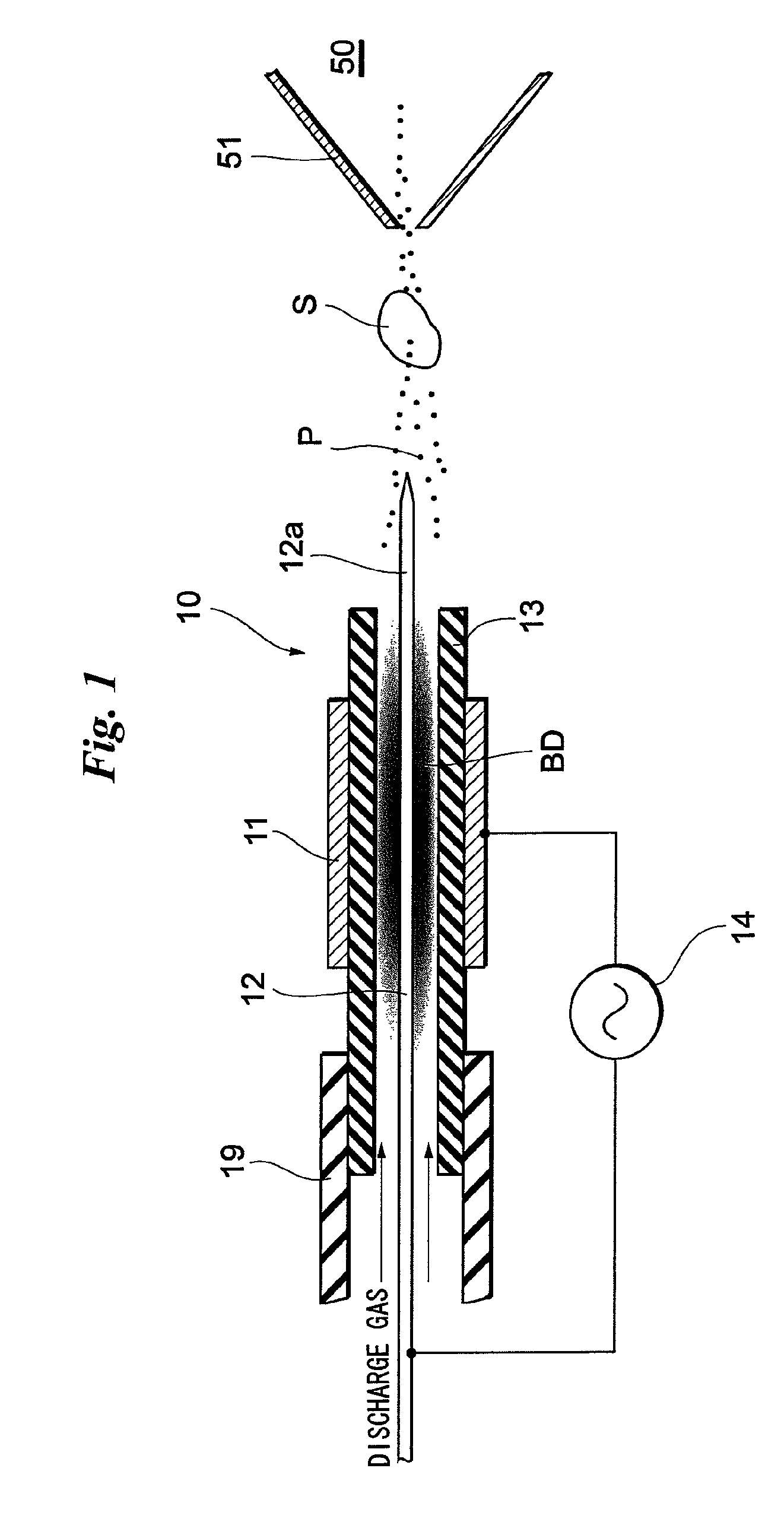
[0054]FIG. 1 illustrates the principle of ionization according to the present invention and shows an arrangement of an ionization apparatus and ionization analysis apparatus according to a first embodiment of the present invention.

[0055]Sample ions that have been ionized by the ionization method and apparatus according to the present invention (ions of particles such as atoms and molecules desorbed from a sample) are introduced to and analyzed by a mass analyzer. The apparatus (method) of the embodiments is mainly classified broadly into that of a spray type (or blow type) and that of a suction type depending upon a difference in the principle according to which the sample ions are introduced to the mass analyzer. The principle of ionization is the same in both types. The first embodiment relates to the spray-type arrangement.

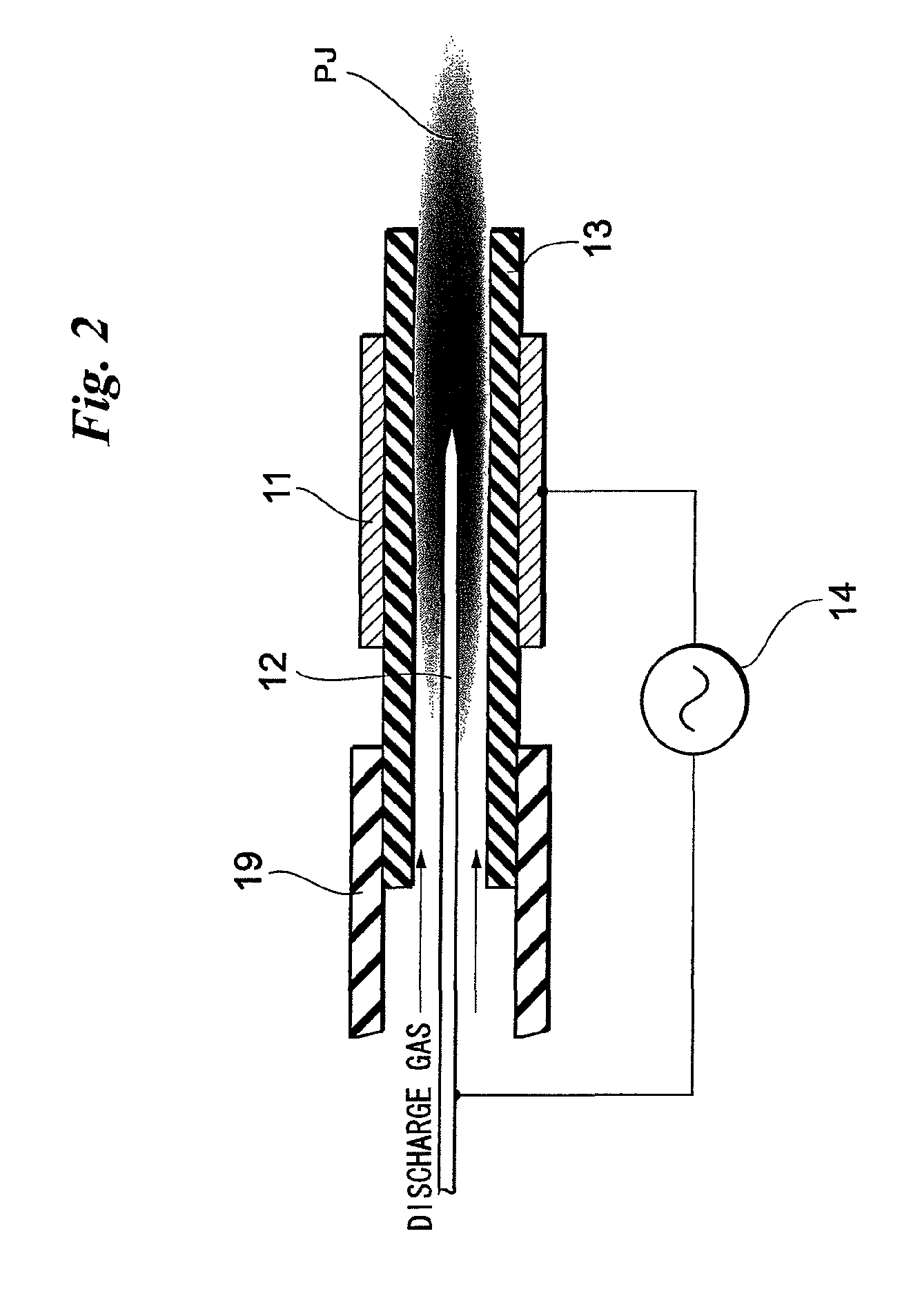
[0056]In FIG. 1, an ionization apparatus 10 includes a cylindrical body 13 comprising a dielectric (or insulator) (e.g., a ceramic or glass, etc.); an annular ...

second embodiment

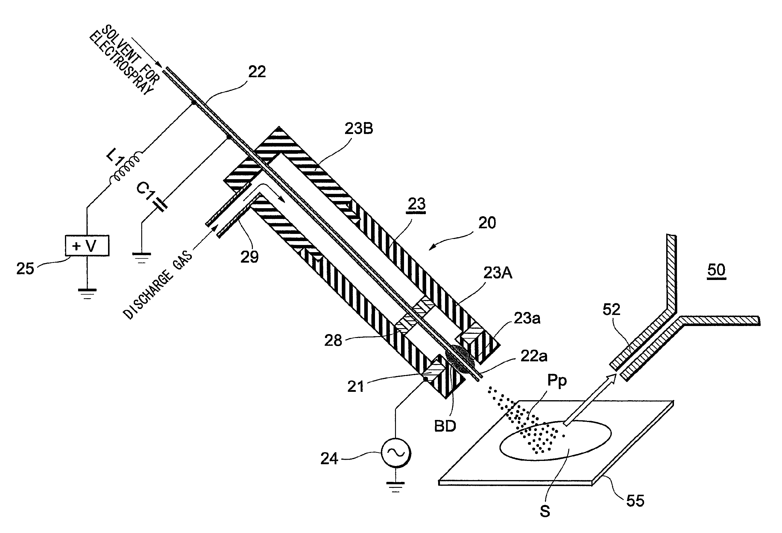
[0081]FIG. 11 illustrates an arrangement of an ionization apparatus and ionization analysis apparatus according to a second embodiment. This apparatus also is of the spray type. Since the basic configuration of the apparatus and the ionization principle thereof are the same as described in the first embodiment, the aspects of this embodiment that differ will be described below.

[0082]Ionization apparatus (ionization analysis apparatus) 20 includes a cylindrical body 23 made of a dielectric and comprising a first half 23A and a second half 23B. The portions 23A, 23B are joined by being fitted together or screwed together or joined by some other method. The distal end of the cylindrical body 23 (first half 23A) is formed to be somewhat thick and is provided with a somewhat small center hole 23a. The outer peripheral surface of the thickly formed distal end of cylindrical body 23 (first half 23A) is formed to have an annular groove into which a first electrode (annular electrode) 21 has...

third embodiment

[0108]FIG. 19 illustrates the basic arrangement of an ionization apparatus and ionization analysis apparatus according to a third embodiment. The third embodiment is a type in which ionized sample ions are drawn into a mass analyzer utilizing the vacuum system of the mass analyzer.

[0109]In an ionization apparatus (ionization analysis apparatus) 30, a second electrode 32 serves also as an ion sampling capillary of the mass analyzer 50. The capillary 32 is made of metal (or a conductor), as a matter of course. A cylindrical body 33 made of a dielectric is placed about the periphery of the capillary 32 leaving a clearance between them and is supported on the capillary 32. A discharge-gas supply tube 39 is connected to the base end of the cylindrical body 33, and a discharge gas is supplied to the cylindrical body 33. An annular-shaped first electrode 31 is provided about the outer peripheral surface of the cylindrical body 33 near the distal end portion thereof. An AC high voltage is i...


PUM


Abstract

An ionization apparatus comprises a first electrode provided on the outer periphery of a dielectric cylindrical body and a second cylindrical electrode placed inside at a center of the cylindrical body. When an AC high voltage is impressed across the first electrode and the second cylindrical electrode, a barrier discharge occurs within the cylindrical body. A distal end portion of the second cylindrical electrode projects outwardly from the distal end of the cylindrical body, a thermal equilibrium plasma P having a low electron temperature is generated outwardly from the distal end of the cylindrical body without a plasma jet ascribable to the barrier discharge emerging outwardly from the distal end of the cylindrical body. By exposing a sample S to the thermal equilibrium plasma P, particles (atoms, molecules) desorbed from the sample S undergo soft ionization without being decomposed or polymerized.

Description

TECHNICAL FIELD[0001]This invention relates to an atmospheric-pressure ionization analysis method and apparatus utilizing barrier discharge.BACKGROUND ART[0002]Examples of an ionization analysis method and apparatus utilizing barrier discharge are described in the following literature:[0003]1. Na Na, Chao Zhang, Mengxia Zhao, Sichun Zhang, Chengdui Yang, Xiang Fang and Xinrong Zhang, “Direct detection of explosives on solid surfaces by mass spectrometry with an ambient ion source based on dielectric barrier discharge”, J. Mass Spectrom. 2007; 42:1079-1085[0004]2. Na Na, Mengxia Zhao, Sichun Zhang, Chengdui Yang and Xinrong Zhang, “Development of a Dielectric Barrier Discharge Ion Source for Ambient Mass Spectrometry”, J Am Soc Mass Spectrom. 2007, 18, 1859-1862[0005]The ion analysis method and apparatus described in these references have a plate-shaped electrode, a glass plate placed on the surface of the plate-shaped electrode and a needle-shaped electrode disposed substantially pe...

Claims


Application Information

Patent Timeline
Patent Type & Authority Patents(United States)
IPC IPC(8): H01J49/10
CPCH01J49/165H01J49/105H01J49/142H05H1/2406H05H1/2443
Inventor HIRAOKA, KENZOCHEN, LEE CHUIN
Owner UNIVERSITY OF YAMANASHI
Why Eureka
Try Eureka