

High-position branch pruning device
A pruning device and a branch technology, applied in the field of high-altitude branch pruning devices, can solve the problems of inability to trim and shape tree struts, high pruning efficiency, good molding effect, etc., and achieve high pruning efficiency, saving time and labor costs, and good molding effect. Effect
- Summary
- Abstract
- Description
- Claims
- Application Information
AI Technical Summary
Problems solved by technology
Method used
Image

Examples
specific Embodiment approach 1
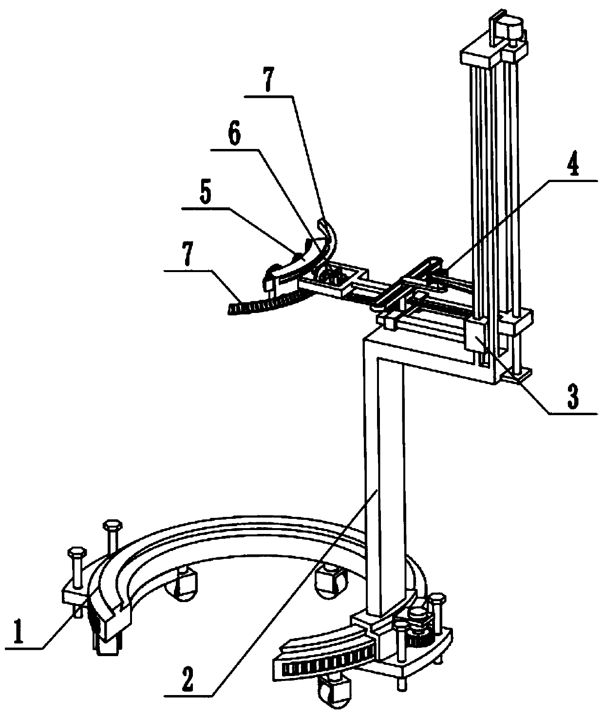
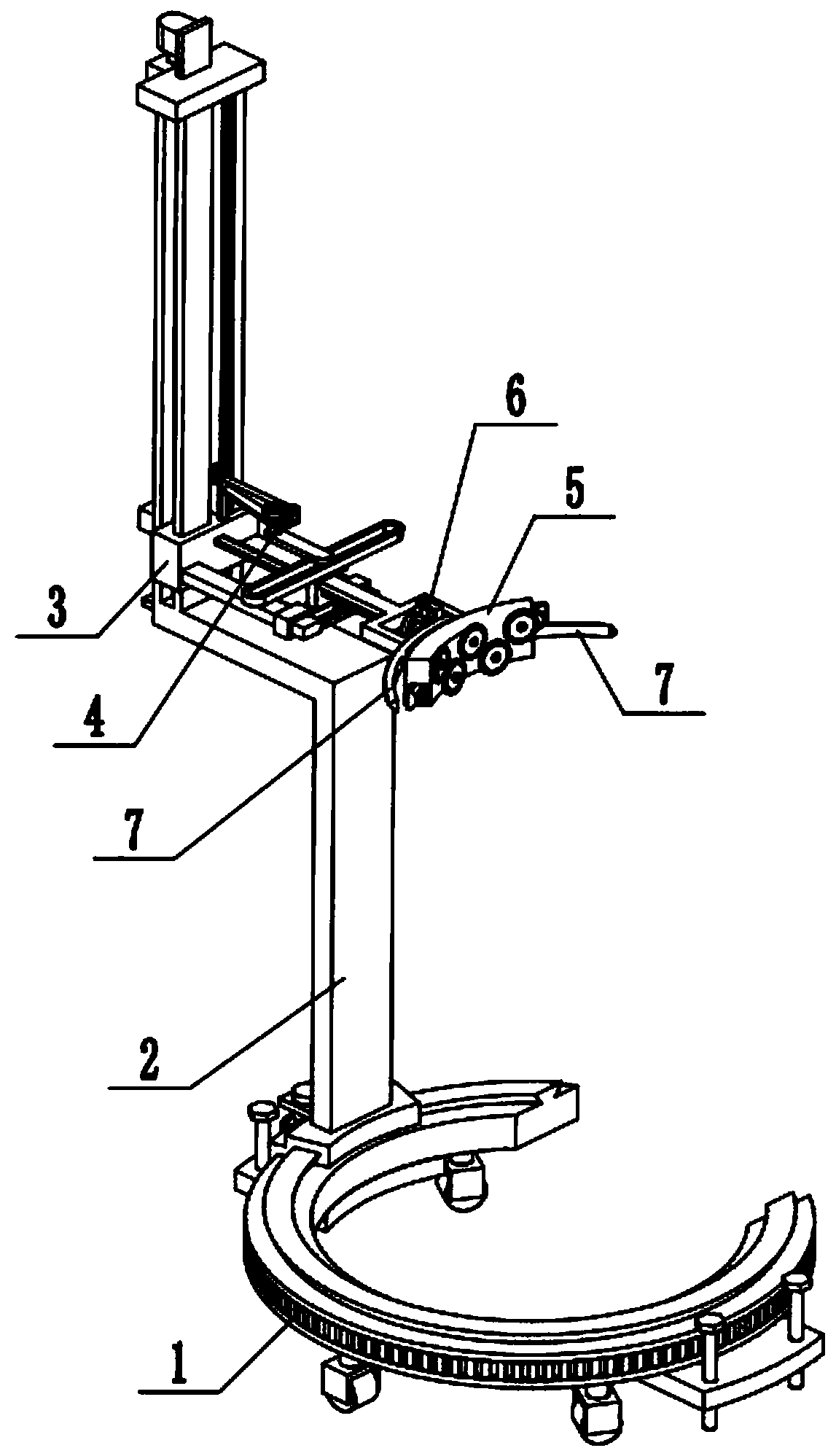
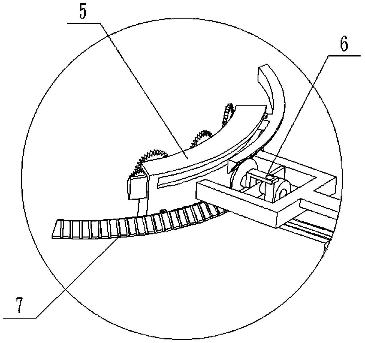
[0031] Combine below Figure 1-9 Description of this embodiment, a high-altitude tree branch pruning device, including a support base 1, a frame 2, a radial adjustment mechanism 3, a lateral adjustment mechanism 4, a fixed pruning mechanism 5, a linkage wheel assembly 6 and a telescopic pruning mechanism 7, the described The frame 2 is slidingly fitted and connected to the support base 1, and the frame 2 is meshed with the support base 1 for transmission connection. The radial adjustment mechanism 3 is slidingly fitted and connected to the frame 2. The radial adjustment mechanism 3 is connected to the frame 2 through screw fit. , the horizontal adjustment mechanism 4 is arranged on the radial adjustment mechanism 3, the horizontal adjustment mechanism 4 is meshed with the support base 1 and connected in transmission, the fixed pruning mechanism 5 is fixedly connected to the horizontal adjustment mechanism 4, and the linkage wheel assembly 6 is fixedly connected to the fixed pru...
specific Embodiment approach 2
[0033] Combine below Figure 1-9 To illustrate this embodiment, the support base 1 includes an annular seat 1-1 with an open front end, a trapezoidal slide rail 1-2 distributed in a circle, a universal wheel 1-3, a screw seat plate 1-4, and a ground screw 1 -5 and the open ring gear 1-6 at the front end; the top surface of the annular seat 1-1 is fixedly connected to the trapezoidal slide rail 1-2, and the lower end of the annular seat 1-1 rotates evenly and is connected with a plurality of universal wheels 1-3, two A screw seat plate 1-4 is symmetrically fixedly connected to the bottom surface of the ring seat 1-1; the screw seat plate 1-4 is threaded to connect two ground screws 1-5, and the outer end of the ring seat 1-1 is set There is a rack placement groove, and the ring gear 1-6 is fixedly connected in the rack placement groove. When the support base 1 is in use, the opening of the ring seat 1-1 with the front end open is directed towards the root of the tree, and the ...
specific Embodiment approach 3
[0035] Combine below Figure 1-9 To illustrate this embodiment, the frame 2 includes an L-shaped sliding seat 2-1, a motor I2-2, a gear I2-3, an L-shaped frame plate 2-4, a vertical plate 2-5, and a side chute 2-6 , rectangular slot 2-7, shaft frame plate 2-8, adjusting screw 2-9, motor Ⅱ 2-10 and rack Ⅰ 2-11; L-shaped sliding seat 2-1 is slidingly fitted and connected to ring seat 1-1 and trapezoidal On the slide rail 1-2, the motor I2-2 is fixedly connected to the L-shaped sliding seat 2-1 through the motor frame, the output shaft of the motor I2-2 is fixedly connected to the gear I2-3, and the lower end of the L-shaped sliding seat 2-1 is set There are gears through the slots, the gear I2-3 passes through the gears through the slots and meshes with the ring gear 1-6 for transmission connection, and the two ends of the L-shaped frame plate 2-4 are respectively fixedly connected to the L-shaped sliding seat 2-1 and the vertical plate 2-5 , a side chute 2-6 is arranged on bot...
PUM
 Abstract
Description
Claims
Application Information