Alga graded filtering device for removing algae in coupling manner

A technology of graded filtration and algae, applied in the direction of filtration separation, fixed filter element filter, separation method, etc., can solve the problems that algae cannot be discharged through graded filtration, and algae clogging cannot be prevented, so as to achieve the effect of preventing clogging

Pending Publication Date: 2019-07-23
HEILONGJIANG LANDE ULTRASONIC TECH CO LTD
View PDF7 Cites 4 Cited by
  • Summary
  • Abstract
  • Description
  • Claims
  • Application Information

AI Technical Summary

Problems solved by technology

However, this equipment cannot prevent the clogging caused by excessive algae, nor can it discharge the algae graded filtration of the liquid containing batches of algae

Method used


Image

  • Alga graded filtering device for removing algae in coupling manner
  • Alga graded filtering device for removing algae in coupling manner
  • Alga graded filtering device for removing algae in coupling manner

Examples


specific Embodiment approach 1

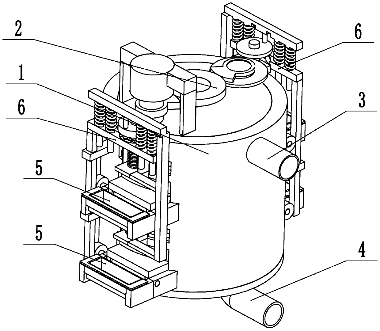
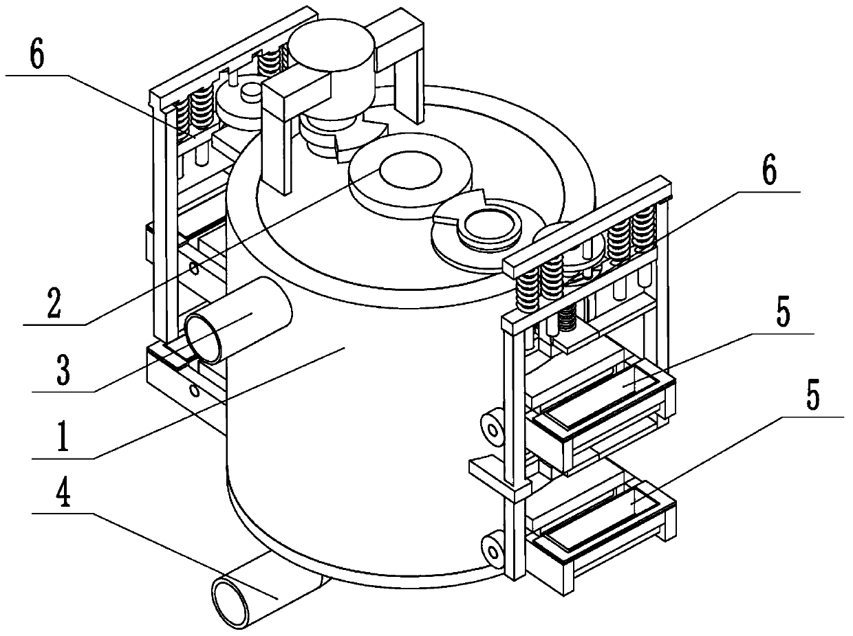
[0031] Such as Figure 1 to Figure 11 As shown, an algae grading filter device for coupling algae removal includes an algae sub-filter tank 1, a collection driver 2, a feed pipe 3, a liquid recovery pipe 4, four algae recovery frames 5, and two algae recovery pushers 6. The collection driver 2 is rotatably connected to the upper end of the algae sub-filter 1, the feed pipe 3 and the liquid recovery pipe 4 are respectively fixedly connected and communicated with the upper and lower ends of the algae sub-filter 1, and the left and right sides of the collection driver 2 The four algae recovery frames 5 are respectively arranged on the outer wall of the algae sub-filter 1, and the two algae recovery propellers 6 are connected to the side of the algae sub-filter 1 respectively. Left and right ends. A batch of algae-containing liquid is added to the algae sub-filter 1 through the feed pipe 3, and the collection driver 2 is connected to the power, and the algae in the algae sub-filt...

specific Embodiment approach 2

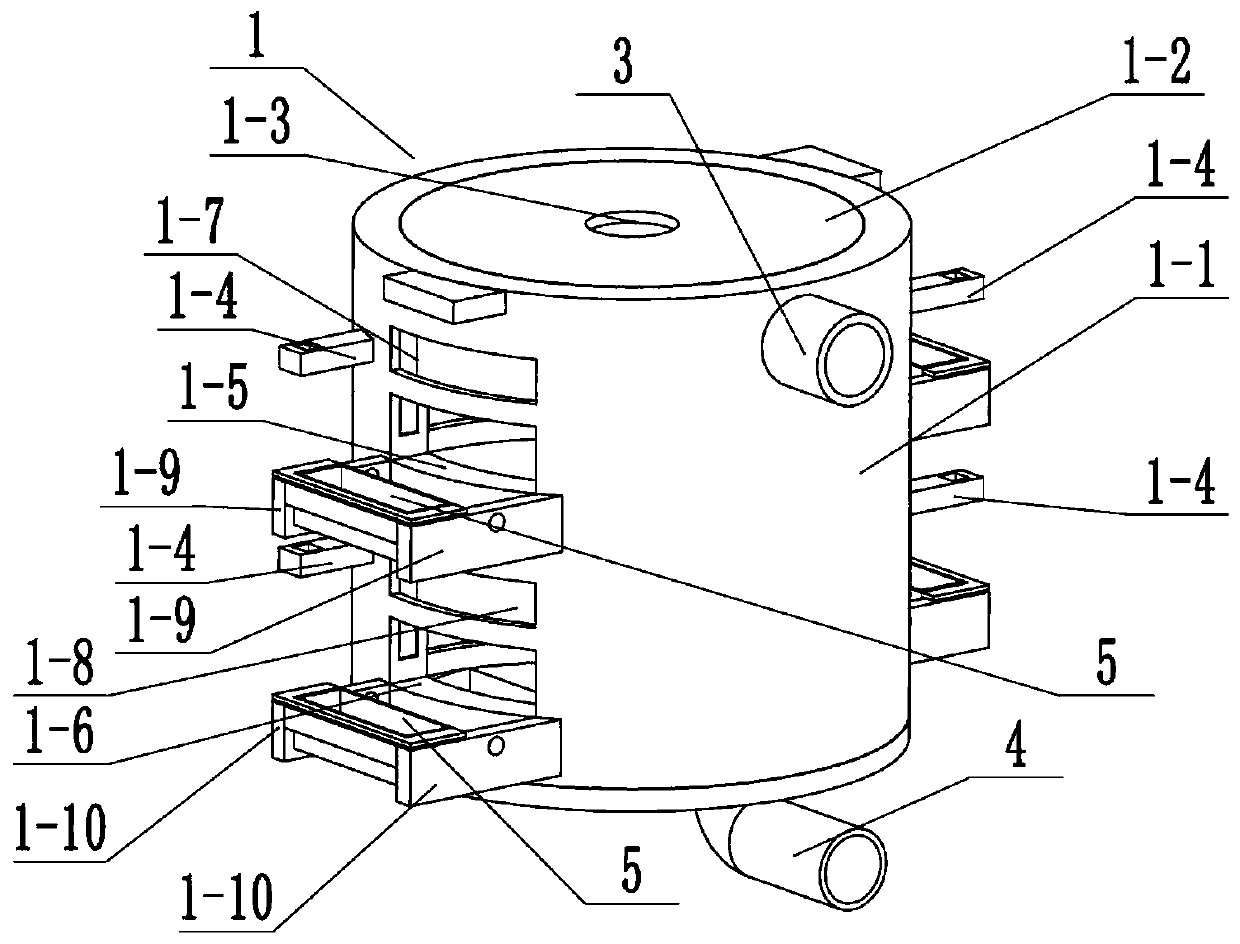
[0033] Such as Figure 1 to Figure 11 As shown, this embodiment will further explain Embodiment 1. The algae filter tank 1 includes a tank body 1-1, an upper end cover 1-2, a central rotating hole 1-3, and four rack sliding positioning rods 1 -4. Two upper discharge outlets 1-5, two lower discharge outlets 1-6, two upper valve chutes 1-7, two lower valve chutes 1-8, four upper fixed connecting rods 1 -9 and four lower fixed connecting rods 1-10, the upper end of the tank body 1-1 is fixedly connected to the upper end cover 1-2, and the central rotating hole 1-3 is arranged at the center of the upper end cover 1-2, and the tank body The left and right ends of 1-1 are respectively fixedly connected with two rack sliding positioning rods 1-4, the two upper discharge outlets 1-5 are respectively arranged on the upper sides of the left and right ends of the tank body 1-1, and the two lower discharge outlets 1-6 are respectively arranged on the lower side of the left and right ends...

specific Embodiment approach 3

[0035] Such as Figure 1 to Figure 11 As shown, this embodiment will further illustrate Embodiment 2. The algae separation filter tank 1 also includes an upper separation filter plate 1-11, a plurality of coarse separation circular holes 1-12, and two upper recovery push grooves 1-11. 13. The lower sub-filter plate 1-14, multiple fine-separation round holes 1-15 and two lower recovery push grooves 1-16, the upper sub-filter plate 1-11 and the lower sub-filter plate 1-14 are fixed from top to bottom Connected to the inner wall of the tank body 1-1, multiple coarse round holes 1-12 are arranged vertically through the upper filter plate 1-11, and multiple fine round holes 1-15 are arranged vertically through the lower filter plate 1 On -14, two upper recovery push grooves 1-13 are respectively arranged up and down on the left and right ends of the upper sub-filter plate 1-11, and two lower recovery push grooves 1-16 are respectively arranged up and down on the lower sub-filter pl...


PUM


Abstract

The invention relates to the field of sewage purification and more particularly relates to an alga graded filtering device for removing algae in a coupling manner. The alga graded filtering device comprises an alga separate filtering tank, a collection driver, a feeding pipe, a liquid recycling pipe, four alga recycling frames and two alga recycling pushing devices, wherein the collection driver is rotatably connected to the upper end of the alga separate filtering tank; the feeding pipe and the liquid recycling pipe are fixedly connected and communicated to upper and lower ends of the alga separate filtering tank respectively; left and right ends of the collection driver are in intermittent engaged transmission with the two alga recycling pushing devices respectively. The alga graded filtering device provided by the invention has the beneficial effects that the algae in liquid containing batch algae can be filtered and discharged in a graded manner; meanwhile, a phenomenon that blocking is caused by the fact that the liquid contains excessive algae so that the filtering effect is influenced is also prevented.

Description

technical field [0001] The invention relates to the field of sewage purification, in particular to an algae classification filter device for coupling algae removal. Background technique [0002] Patent No. CN201010511034.9 discloses a diatomite filter device for water treatment, the diatomite filter device includes a filter, pressure monitoring equipment, five-way valves, pressurization equipment, diatomite adding equipment and pipelines . Among them, the filter is a plate-and-frame structure with at least two filter layers, and the two surfaces of the filter layers are coated with diatomaceous earth; the pressure monitoring equipment is arranged on the filter; one channel of the five-way valve passes through the pipeline Connected with pressurized equipment, two passages are respectively connected to the inlet and outlet of the filter through pipelines, one passage is used to discharge filtered water through the pipeline, and the other passage is used to discharge backwash...

Claims


Application Information

Patent Timeline
Patent Type & Authority Applications(China)
IPC IPC(8): B01D29/03B01D29/58B01D29/64B01D29/94
CPCB01D29/03B01D29/58B01D29/6415B01D29/94
Inventor 陈光甡祝金磊侯晓丹吕强迟毅李伟关丽娜
Owner HEILONGJIANG LANDE ULTRASONIC TECH CO LTD
Why Eureka
Try Eureka