
Automatic spinning mechanism for spinning frame

A spinning frame and yarn technology, applied in the textile field, can solve the problems of affecting the workshop environment, shaking of the control box, and falling of fiber flying flowers, etc., and achieve the effects of increasing work efficiency, good shock absorption effect, and simple operation.

Inactive Publication Date: 2019-07-23
JIANGSU NIJIAXIANG GROUP WORSTED TEXTILE
View PDF0 Cites 0 Cited by
  • Summary
  • Abstract
  • Description
  • Claims
  • Application Information

AI Technical Summary

Problems solved by technology

[0004] In the spinning frame currently on the market, the general roving packages are put in as a whole, but when a single or a certain part of the roving package is used up, it needs to be replaced as a whole, which causes a lot of waste of roving resources and increases the production cost. , unable to make full use of the roving
[0005] And the control box will shake during normal operation. If the shaking is too large, it will affect the smoothness of the track mechanism.
[0006] When the yarn machine is spinning in the spinning area, the rovings are often broken and the fiber fly falls off. These rovings and fiber fly fall on the machine not only affect the workshop environment, but also may be wound on the rollers and top rollers. Affect the normal operation of the equipment

Method used


Image

  • Automatic spinning mechanism for spinning frame
  • Automatic spinning mechanism for spinning frame
  • Automatic spinning mechanism for spinning frame

Examples


Embodiment Construction

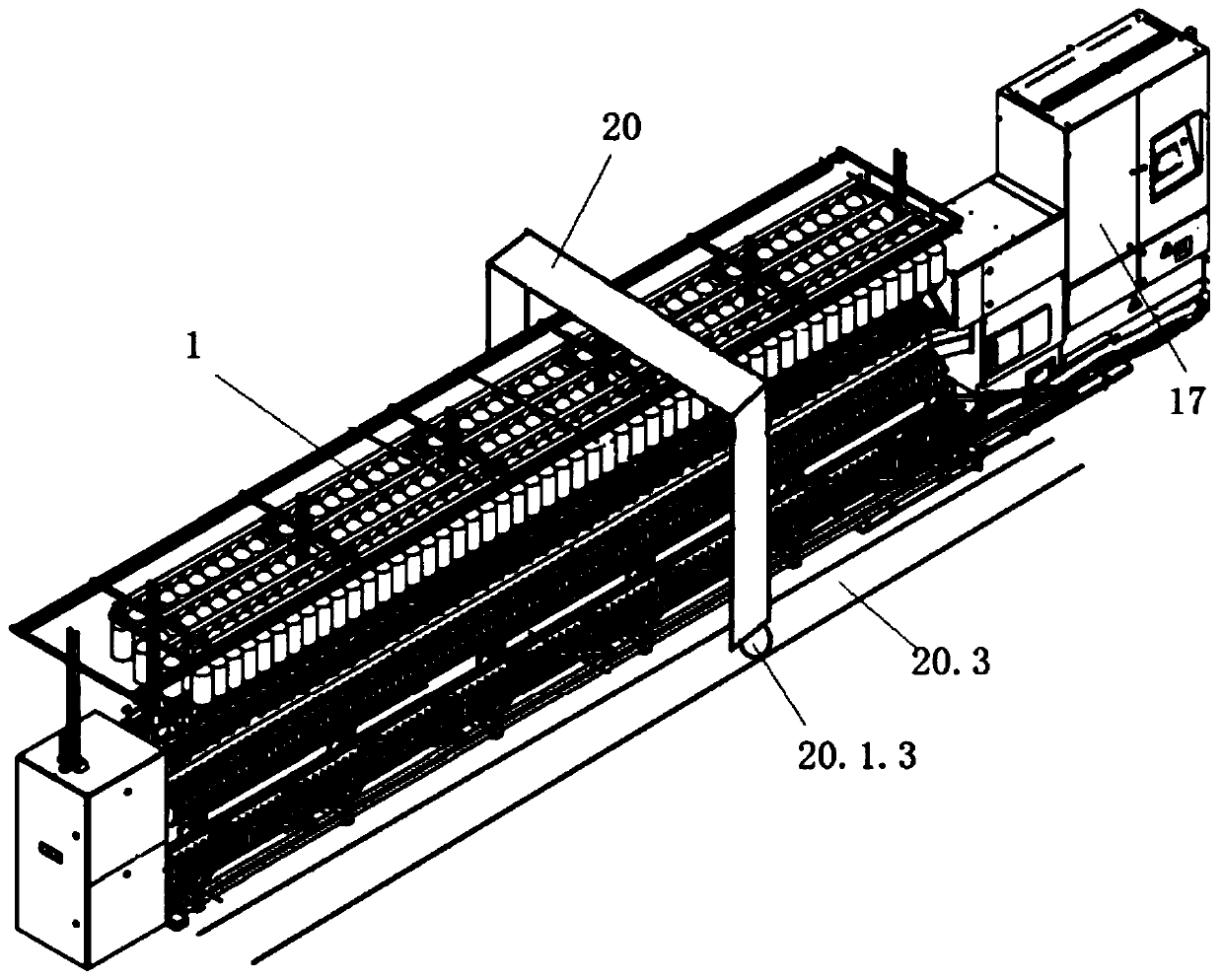
[0029] see Figure 1 to Figure 8 , The present invention relates to an automatic spinning mechanism of a spinning frame, comprising a spinning frame body 1 , a control box 17 , a shock absorbing device 18 and a wool suction mechanism 20 .

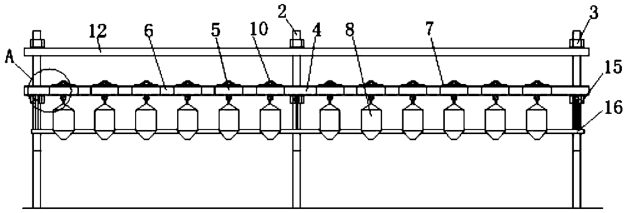
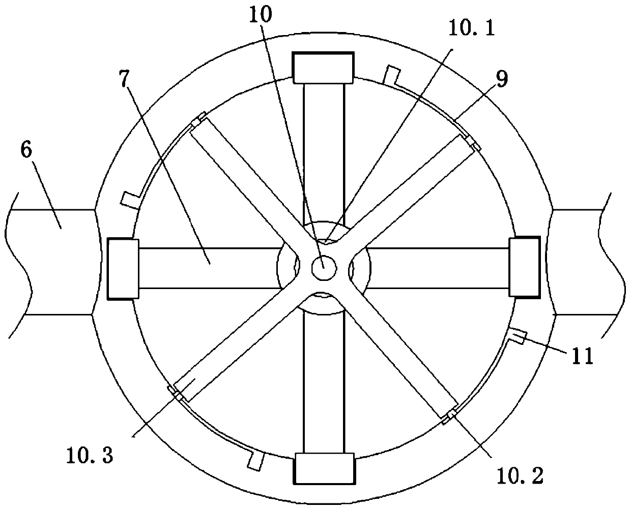
[0030] A roving creel cross bar 2 is installed on the top of the spinning frame body 1, and the roving creel cross bar 2 is provided with two upper and lower horizontally arranged roving creel support rods 3, and the bottom end of the roving creel support rod 3 is equipped with a spindle hanger cross bar 4. A holding support ring 5 is set between two adjacent hanging ingot crossbars 4, and the holding support ring 5 is fixed by the connecting rod 6. The top of the holding support ring 5 is clamped with the hanging ingot 7, and the bottom of the hanging ingot 7 end runs through and extends to the bottom of the holding support ring 5, the bottom end of the hanging spindle 7 is hooked with a roving package 8, and the top of the holding support...


PUM


Abstract

The invention relates to an automatic spinning mechanism for a spinning frame. Containing supporting rings are connected through bobbin hanger transverse rods and connecting rods, so that the containing supporting rings are fixed to creel supporting rods; crossed fixing sliding rods which are rotationally connected with the tops of the bobbin hanger transverse rods are slidably connected with sliding grooves in the tops of the containing supporting rings, so that bobbin hangers are fixed to the containing supporting rings. Because the tops of rove packages are hung on the bobbin hanger, when asingle one or part of the rove packages need to be replaced, replacement can be conducted, the situation that when a whole row of rove packages is replaced to cause wasting of rove is avoided, and the production cost is reduced. A vibration reduction device is arranged on the bottom of a control box, and the vibration reduction effect is better; fabric dust attracting mechanisms are arranged on the front side and the rear side of the spinning frame, the fabric dust attracting mechanisms can parallelly move along a spinning area, therefore, nozzles close to the spinning area of the spinning frame are driven to suck air, disconnected rove and fiber flyings are drawn away, a shop environment is prevented from being contaminated, rollers and leather rollers are prevented from being wound withthe rove and the fiber flyings, and normal running of the device is ensured.

Description

technical field [0001] The invention relates to an automatic spinning mechanism of a spinning frame, which belongs to the technical field of textiles. Background technique [0002] Semi-worsted spinning has developed rapidly in recent years, and many wool spinning mills have added semi-worsted spinning equipment. Antibacterial blended fabrics are an important fabric, which needs to be processed by spinning machines during production. [0003] The spinning frame is the main machine for spinning, and the yarn bobbin is also the main tool for yarn winding. During the spinning process, the semi-finished roving or sliver is drawn, twisted, and wound into a spinning machine and sliver. The roving is drawn and twisted on the roving frame, the fiber is combed by the combing machine to make a combed sliver, the sliver is combined by the needle card machine, and the structure of the sliver is improved by the needle row drafting, and the roving is further twisted and spun on the ring s...

Claims


Application Information

Patent Timeline
IPC IPC(8): D01H11/00D01H9/02D01H7/08F16F15/04
CPCD01H7/08D01H9/02D01H11/006F16F15/04
Inventor 葛立平倪学忠孙秋亚李玲
Owner JIANGSU NIJIAXIANG GROUP WORSTED TEXTILE
Learn More