
Flow guiding and cooling system comprising fan and flow guiding structure

A diversion cooling and fan technology, applied in engine cooling, engine components, machines/engines, etc., can solve the problems of reducing fan air volume and efficiency, large back pressure, etc., to improve airflow direction, increase efficiency, and reduce exhaust The effect of pressure

Pending Publication Date: 2019-07-23
SUZHOU RISING AUTO PARTS
View PDF0 Cites 0 Cited by
  • Summary
  • Abstract
  • Description
  • Claims
  • Application Information

AI Technical Summary

Problems solved by technology

[0004] In the prior art, the airflow guiding structure of the cooling fan mainly considers diversion in the air inlet area to improve the air intake pressure, but ignores the influence of the back pressure in the air outlet area on the performance of the fan, especially in the air outlet area. When the airflow cannot be exported in time, it is easy to form a large back pressure, which reduces the air volume and efficiency of the fan

Method used


Image

  • Flow guiding and cooling system comprising fan and flow guiding structure
  • Flow guiding and cooling system comprising fan and flow guiding structure
  • Flow guiding and cooling system comprising fan and flow guiding structure

Examples

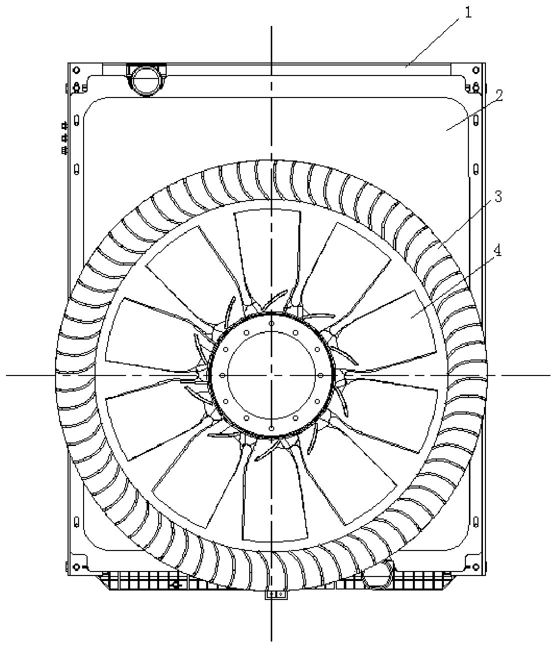
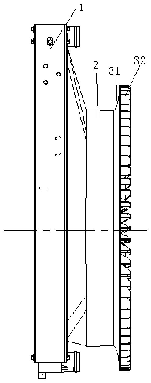
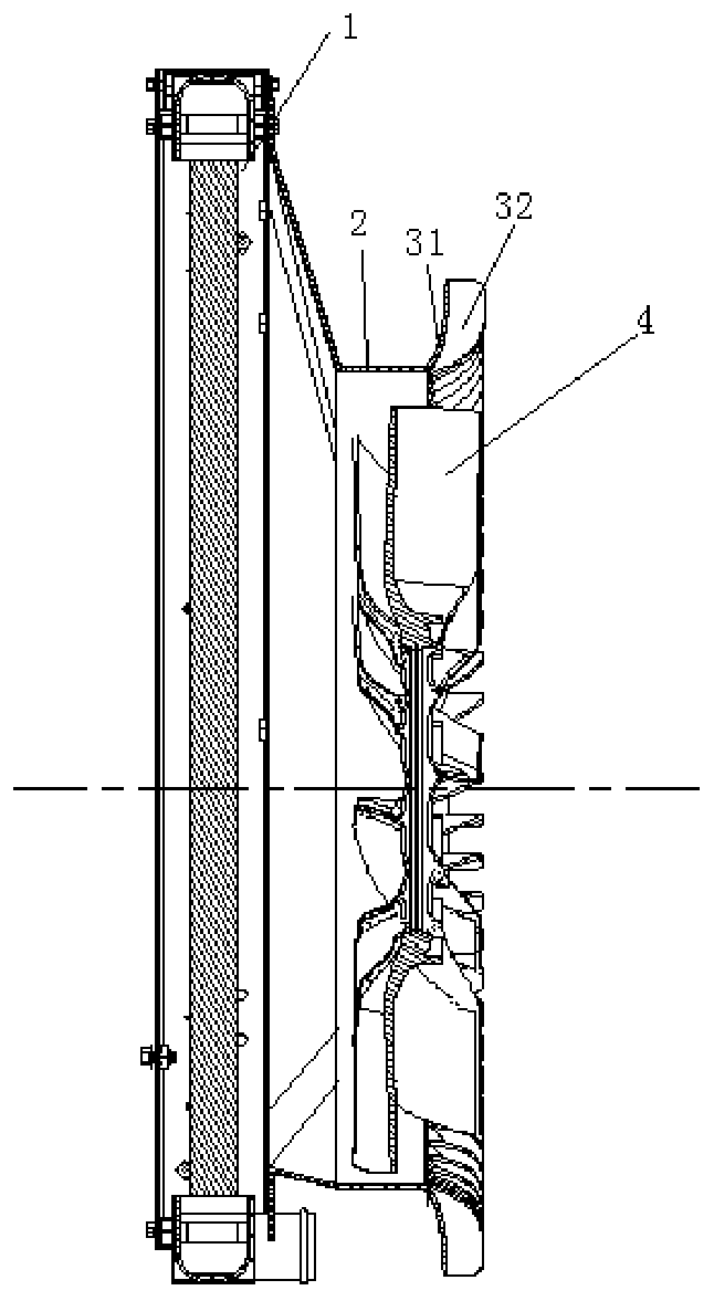

Embodiment

[0024] When the cooling fan 4 rotates, the air is sucked in by the air inlet 61 of the air guide channel at the end of the radiator 1, compressed by the rotation of the fan, and discharged by the air outlet 62 of the air guide channel.

[0025] Such as Figure 5 , Figure 6 As shown, when the cooling fan 4 rotates, in the area of ​​the air outlet 62 of the fan, the air is guided radially outward along the guide vane 32 due to the air outlet guide structure 3, thereby avoiding the "crowding" of the air in the area of ​​the air outlet 62 of the guide channel. ", reducing the exhaust pressure in the area of ​​the air outlet 62 of the diversion channel, indirectly reducing the intake pressure of the air inlet, that is, increasing the air volume of the cooling fan 4 and increasing the efficiency of the cooling fan 4, especially at the outlet of the diversion channel There is a large blocker in the air port 62, such as an engine, the effect of the air outlet guide structure 3 is mo...


PUM


Abstract

The invention discloses a flow guiding and cooling system comprising a fan and a flow guiding structure. The flow guiding and cooling system comprising the fan and the flow guiding structure comprisesa radiator, an air inlet and flow guiding structure, an air outlet and flow guiding structure and the cooling fan. One end of the air inlet and flow guiding structure is fixed to the radiator. The other end of the air inlet and flow guiding structure is connected with the air outlet and flow guiding structure. The cooling fan is arranged in a flow guiding channel formed by the air inlet and flowguiding structure and the air outlet and flow guiding structure in a built-in manner. The air outlet and flow guiding structure comprises a flow guiding ring and flow guiding blades. By using the flowguiding and cooling system comprising the fan and the flow guiding structure, the exhaust pressure at an air outlet is lowered, the air volume of the cooling fan is increased by 8% or more, and therefore, the efficiency of the cooling fan is improved by about 10%.

Description

technical field [0001] The invention relates to the field of cooling systems, in particular to a diversion cooling system composed of a fan and a diversion structure. Background technique [0002] As the cooling system is an important part of the engine compartment, how to improve the cooling system and improve the heat dissipation performance of the compartment is the focus of current research, which determines the fuel economy and emission performance of the engine. [0003] For the engine cooling system, it is necessary to improve the heat dissipation performance of the cabin, optimize the integration of the cooling system, and have practical value and significance for improving fuel economy. In the prior art, the air guide structure is an important sub-component of the air cooling system, and its function is to guide the direction of air when the fan rotates, change the air intake and outlet pressure, and improve the air volume and efficiency of the fan. [0004] In the...

Claims


Application Information

Patent Timeline
IPC IPC(8): F01P5/06
CPCF01P5/06
Inventor 刘敦绿柯彬彬张健
Owner SUZHOU RISING AUTO PARTS
Learn More