Cooling system and projection equipment

A technology for cooling systems and electronic devices, applied in instruments, projection devices, optics, etc., can solve problems such as affecting product reliability and performance, foreign matter splashing in radiators, etc.

Active Publication Date: 2021-07-06
APPOTRONICS CORP LTD
View PDF6 Cites 0 Cited by
  • Summary
  • Abstract
  • Description
  • Claims
  • Application Information

AI Technical Summary

Problems solved by technology

[0005] The invention provides a heat dissipation system and projection equipment to solve the problem in the prior art that foreign matter splashes in the radiator and affects the reliability of the product

Method used


Image

  • Cooling system and projection equipment
  • Cooling system and projection equipment
  • Cooling system and projection equipment

Examples


Embodiment 1

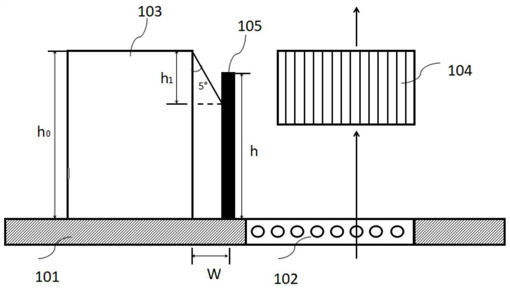
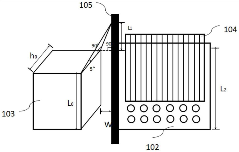
[0042] Such as figure 1 and figure 2 As shown, the heat dissipation system of the present invention includes a housing 101 , an opening area 102 disposed at the bottom of the housing 101 , an electronic device 103 accommodated in the housing 101 , a heat sink 104 and a baffle 105 .

[0043] Wherein the electronic device 103 is an electronic circuit with a power greater than 100W. figure 1 The straight line with the arrow in the middle indicates the flow direction of the wind. The external cold air flows in from the opening area 102 of the bottom shell, passes through the radiator 103, takes away the internal heat, and flows out in the state of internal hot air.

[0044] The baffle 105 is arranged between the electronic device 103 and the opening area 102. The position of the baffle 105 should exceed the edge of the opening area 102 of the casing 101 and is close to the edge of the electronic circuit. The opening area of ​​the enclosure is isolated to avoid the ejection of s...

Embodiment 2

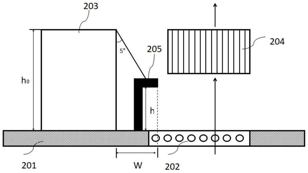
[0069] refer to image 3 As shown, it is the second embodiment of the present invention, which is improved on the basis of the previous embodiments. The principle and structure are roughly the same. The heat dissipation system includes a casing 201, an opening area 202 arranged at the bottom of the The electronic device 203, the heat sink 204 and the baffle 205 in the housing 201 differ only in that the structure of the baffle is different. The baffle in Embodiment 1 is elongated, which can effectively block the potential fire source within a 5° angle range. The molten metal or burning material inside, but due to structural limitations, there is often the problem that there is not much space in the vertical direction of the baffle, so the baffle here is designed as L-shaped in this embodiment.

[0070] Specifically, the baffle includes a longitudinal baffle extending along the longitudinal direction and a transverse baffle bent and extended from the longitudinal baffle, wherei...

Embodiment approach

[0075] refer to Figure 4 As shown, it is the third embodiment of the present invention, which is improved on the basis of the previous embodiments, and its principle and structure are roughly the same. The heat dissipation system includes a housing 301, an opening area 302 arranged at the bottom of The electronic device 303, the heat sink 304 and the baffle 305 in the housing 301 differ only in that the structure of the baffle is different. The baffle in Embodiment 1 is elongated, which can effectively block the potential fire source within a 5° angle range. Molten metal or burning material inside, but due to structural limitations, there is often the problem that there is not much space in the vertical direction of the baffle; while the L-shaped baffle in Embodiment 2 requires a larger width in the horizontal direction, That is to say, W is required to be large, and the minimum width requirement cannot be met if limited by the free structure in the horizontal direction. The...


PUM


Abstract

The present invention provides a heat dissipation system and projection equipment, the heat dissipation system includes a casing with an opening area, an electronic device arranged in the casing, and the opening area arranged in the casing, wherein the heat dissipation system is close to the opening area A baffle is provided for protection, the electronic device is arranged on the side of the baffle away from the opening area, and the baffle prevents flammable substances from passing through the The open area drains. By setting the baffle, it is possible to prevent the foreign matter generated by the high-power electronic device from flying out of the opening area of ​​the casing, thereby igniting the support surface or objects placed adjacent to the device, causing a fire hazard, and at the same time preventing foreign matter from entering the interior of the projection device While affecting the reliability of the product, the present invention can greatly improve the safety and reliability of the projection device.

Description

technical field [0001] The invention relates to the field of mechanical heat dissipation, in particular to a heat dissipation system and projection equipment with the heat dissipation system. Background technique [0002] At present, the home projector market has a very large market potential. Major projector and TV manufacturers also want to occupy a certain share in the home projector market, and products with lighter volume and higher brightness will be more favored by consumers. , but the smaller the product, the denser the internal components. If the heat dissipation is not good, the brightness of the projector will increase with the time of use, and the brightness attenuation will increase. Therefore, higher requirements are placed on the heat dissipation of the machine. [0003] In the prior art, a cooling device is separately added to a device with a higher temperature (such as a DMD), and the shell opening below the radiator allows heat transfer between the radiator...

Claims


Application Information

Patent Timeline
Patent Type & Authority Patents(China)
IPC IPC(8): G03B21/16G03B21/14
CPCG03B21/145G03B21/16G03B21/14
Inventor 谢颂婷后国波刘志娟李屹
Owner APPOTRONICS CORP LTD
Why Eureka
Try Eureka