Variant wing vertical takeoff and landing unmanned aerial vehicle

A technology of vertical take-off and landing and modified wings, which is applied in vertical take-off and landing aircraft, wing adjustment, unmanned aircraft, etc.

Pending Publication Date: 2019-07-26
成都纵横大鹏无人机科技有限公司
View PDF0 Cites 2 Cited by
  • Summary
  • Abstract
  • Description
  • Claims
  • Application Information

AI Technical Summary

Problems solved by technology

[0004] In order to further optimize the structural design of the existing UAV proposed above, in order to solve the problem of difficult take-off and landing of the UAV under the condition of high-efficiency aerodynamics, the present invention provides a variant wing vertical take-off and landing drone

Method used


Image

  • Variant wing vertical takeoff and landing unmanned aerial vehicle
  • Variant wing vertical takeoff and landing unmanned aerial vehicle
  • Variant wing vertical takeoff and landing unmanned aerial vehicle

Examples


Embodiment 1

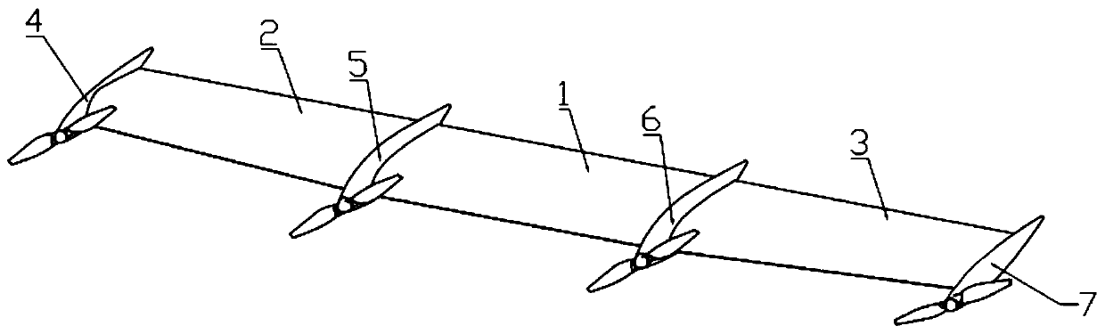
[0047] Such as Figure 1 to Figure 7 As shown, a variant wing vertical take-off and landing UAV includes a UAV body and a plurality of power components installed on the UAV body, the UAV body includes wings, and the power components use For generating thrust or pulling force along the longitudinal direction of the UAV body, the power components are arranged along the transverse direction of the UAV body;

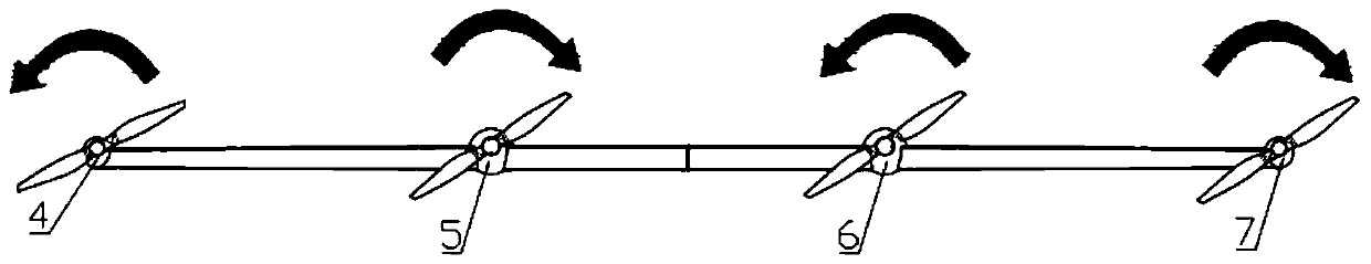
[0048] In the lateral direction of the UAV body, the UAV body is composed of a plurality of sub-sections in series, and any two adjacent sub-sections can be flipped relative to each other, and the direction of the flip axis of the flip is: one end faces the The front end of the man-machine body and the other end face the rear end of the drone body;

[0049] There are at least three power assemblies, and the power assemblies are distributed on different subsections.

[0050] For the existing traditional fixed-wing UAVs: Although the fixed-wing UAVs have the advantages of high...

Embodiment 2

[0055] The present embodiment is further limited on the basis of embodiment 1, as Figure 1 to Figure 7 As shown, as a specific implementation form of the subsection, the subsection includes the first wing 2, the second wing 1 and the third wing 3 arranged in sequence along the lateral direction of the drone body. Power components are fixed on the first wing 2, the second wing 1 and the third wing 3;

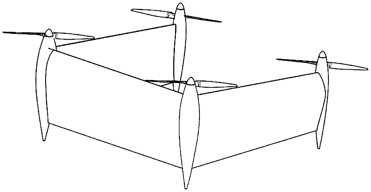
[0056] The axial direction of the turning axis is along the longitudinal direction of the drone body, and the relative turning can be turned so that the first wing 2, the second wing 1 and the third wing 3 are on the same plane. In this solution, by defining the axial direction of the turning axis, the corresponding wings of the UAV can be parallel to the output direction of the power assembly no matter during the take-off and landing multi-rotor flight process or the fixed-wing flight process, so that , to facilitate the optimization of the resistance of the UAV during flight....

Embodiment 3

[0066] Such as Figure 7 As shown, more specifically, this solution provides a wing folding mechanism with self-locking function and a specific solution: it also includes a wing folding mechanism for realizing the relative turning, and the wing folding mechanism includes a drive Motor 13, transmission shaft 15 and worm gear 16 worm screw 17 mechanism, described transmission shaft 15 is connected with the output end of driving motor 13, under the effect of driving motor 13, described transmission shaft 15 can rotate around self axis;

[0067] Described worm wheel 16 worm screw 17 mechanism comprises worm wheel 16 and the worm screw 17 that matches with described worm wheel 16, and described worm screw 17 links to each other with transmission shaft 15, and worm screw 17 is coaxial with transmission shaft 15;

[0068] A worm gear shaft 18 is coaxially installed on the worm gear 16;

[0069]Also include the second connecting lug, in the two subsections connected by the wing foldi...


PUM


Abstract

The invention discloses a variant wing vertical takeoff and landing unmanned aerial vehicle. The variant wing vertical takeoff and landing unmanned aerial vehicle comprises an unmanned aerial vehiclebody and a plurality of power assemblies installed on the unmanned aerial vehicle body; the unmanned aerial vehicle off and landing can be optimized. le body includes wings, the power assemblies are used for generating thrust or pull in the longitudinal direction of the unmanned aerial vehicle body, and the power assemblies are arranged in the transverse direction of the unmanned aerial vehicle body; in the transverse direction of the unmanned aerial vehicle body, the unmanned aerial vehicle body is formed by connecting a plurality of subsections in series, and any two adjacent subsections canbe overturned oppositely, and the directions of an overturned shaft is that one end is towards the front end of the unmanned aerial vehicle body, the other end is towards the rear end of the unmannedaerial vehicle body; and the number of power assemblies is at least three, and the power assemblies are distributed in different subsections. According to the unmanned aerial vehicle, the problem ofmaneuverability of unmanned aerial vehicle taking off and landing can be solved, and stability and control performance of the unmanned aerial vehicle in the process of taking off and landing.

Description

technical field [0001] The invention relates to the technical field of unmanned aerial vehicles, in particular to a modified wing vertical take-off and landing unmanned aerial vehicle. Background technique [0002] The application fields of UAVs are extremely wide, especially in the fields of surveillance, reconnaissance and surveying and mapping. At present, UAVs can be roughly divided into fixed-wing UAVs, unmanned helicopters, multi-rotor UAVs and vertical take-off and landing UAVs (VTOL). Fixed-wing UAVs and vertical take-off and landing UAVs (VTOL) generate aerodynamic lift through the wings, which are superior to rotary-wing UAVs in terms of range, speed, and ceiling. The requirements are high and there are many restrictions. Although the vertical take-off and landing UAV (VTOL) can meet the function of fixed-wing vertical take-off and landing, the hovering power component in the fixed-wing state will cause large dead weight and aerodynamic resistance, which reduces t...

Claims


Application Information

Patent Timeline
Patent Type & Authority Applications(China)
IPC IPC(8): B64C3/38B64C27/22B64C27/26B64C29/00
CPCB64C3/38B64C27/22B64C27/26B64C29/00B64U10/00
Inventor 王利光田裕夫
Owner 成都纵横大鹏无人机科技有限公司
Why Eureka
Try Eureka