
a delta wing aircraft

An aircraft and delta wing technology, applied in the field of unmanned aerial vehicles, can solve the problems of easy occurrence of danger, unchangeable wingspan, and high difficulty of landing on the water surface, and achieve the improvement of flight safety and reliability, superior environmental adaptability, and superior aerodynamic performance. Effect

Active Publication Date: 2016-08-03
LINYI HI TECH ZONE XIANGHONG ELECTRONICS SCI & TECH CO LTD
View PDF7 Cites 0 Cited by
  • Summary
  • Abstract
  • Description
  • Claims
  • Application Information

AI Technical Summary

Problems solved by technology

[0004] 1. Civilian aircraft are mostly multi-axis aircraft and unmanned helicopters, which mainly complete some low-speed aerial photography and agricultural plant protection tasks. Most of these drones have a single purpose, low speed, and short range, which cannot achieve multi-functional and large range. mission
[0005] 2. The steering gear of some aircraft models or aircrafts also uses exposed connecting rods to drive the steering gear to adjust the attitude in the air, which is not beautiful, and at the same time, when the external connecting rods are entangled with other objects or collided with other objects during take-off and landing in complex terrain, it is very dangerous.
After most aircraft are manufactured, their wingspan cannot be changed, which makes it difficult for the aircraft to adapt to the needs of multi-environment and multi-purpose
[0006] 3. Most of the aircraft still rely on manual operation of the controller to fly, which has high requirements for the operator's operating level
For the environment, the requirements such as visibility and wind speed are relatively high; most of the landing methods of UAVs are parachuting, which requires an open field and will inevitably cause damage to the aircraft itself
[0007] 4. At present, there is no unmanned aerial vehicle on the market that can take off and land on the water, because the water surface has high requirements for the waterproof performance of the drone, and the water surface landing is more difficult

Method used


Image

  • a delta wing aircraft
  • a delta wing aircraft
  • a delta wing aircraft

Examples


Embodiment Construction

[0028] The present invention will be further described below in conjunction with the drawings.

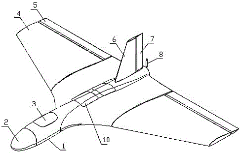
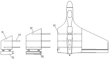
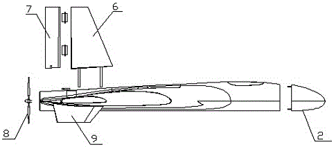
[0029] Such as figure 1 The front end of the fuselage 1 shown is equipped with a detachable load compartment 2, and an energy storage compartment and a navigation control compartment 3 are arranged inside. The energy storage compartment is specifically a battery slot with a movable position. The position of the battery needs to be changed due to the weight of the load. To adjust the center of gravity of the entire aircraft to maintain balance. The navigation control cabin 3 is equipped with a self-developed navigation flight control system, a parachute cabin 10 is installed in the middle of the fuselage, and a propeller 8 driven by a high-speed motor is installed at the rear as a power unit of the aircraft. Triangular wings 4 with ailerons 5 are arranged on both sides of the fuselage 1. The leading edge sweep angle of the wing 4 is 35°. This small-angle leading edge sweep angle can ad...


PUM


Abstract

The invention provides a delta-wing aircraft, comprising a fuselage, a detachable load cabin is arranged at the front end of the fuselage, an energy storage cabin and a navigation control cabin are arranged inside, a parachute cabin is arranged in the middle, and a power device is arranged at the rear; The upper part is provided with a vertical tail with a steering rudder, and the fuselage is provided with a triangular wing with 2 sets of ailerons, and the steering rudder and the 2 sets of ailerons are controlled by 3 sets of built-in steering gear systems; Two vertical stabilizers are arranged symmetrically below the fuselage, and buoys can also be installed on the vertical stabilizers. The invention can realize high-speed navigation, facilitate the replacement of various task loads, fully enclosed and variable wingspan, realize amphibious take-off and landing by using the wing-ground effect, automatically adjust the flight and can be remotely controlled by a computer, and has powerful functions and strong adaptability.

Description

Technical field [0001] The invention relates to an unmanned aerial vehicle, in particular to a delta wing aerial vehicle. Background technique [0002] When the aircraft is flying close to the ground or water surface, the airflow will flow backward and downward after passing through the wings. At this time, the ground or water surface will produce a reaction force, when it is flying at a height equal to or less than 1 / 2 wingspan from the water At this time, the pressure difference between the upper and lower sides of the entire body increases, the lift will suddenly increase, and the drag will decrease, preventing the aircraft wing from falling. This physical phenomenon, which can reduce the induced drag of the aircraft, and at the same time obtain a higher lift-to-drag ratio than air flight, is called the ground effect or the wing-to-ground effect by scientists. [0003] With the development of drone technology, the application of drones has become more and more extensive, but th...

Claims


Application Information

Patent Timeline
Patent Type & Authority Patents(China)
IPC IPC(8): B64C1/00B64C3/26B64C3/38B64C35/00B64C5/06
Inventor 毛有斌
Owner LINYI HI TECH ZONE XIANGHONG ELECTRONICS SCI & TECH CO LTD
Learn More