
A metal wire winding device

A technology of winding device and metal wire, which is applied in transportation and packaging, thin material processing, transportation of filamentous materials, etc. and easy to replace effects

Active Publication Date: 2020-09-22
天长市恒鑫机电设备有限公司
View PDF12 Cites 0 Cited by
  • Summary
  • Abstract
  • Description
  • Claims
  • Application Information

AI Technical Summary

Problems solved by technology

[0003] The purpose of the present invention is to solve the problem of labor-intensive and low efficiency in the prior art, and propose a metal wire winding device

Method used


Image

  • A metal wire winding device
  • A metal wire winding device
  • A metal wire winding device

Examples


Embodiment 1

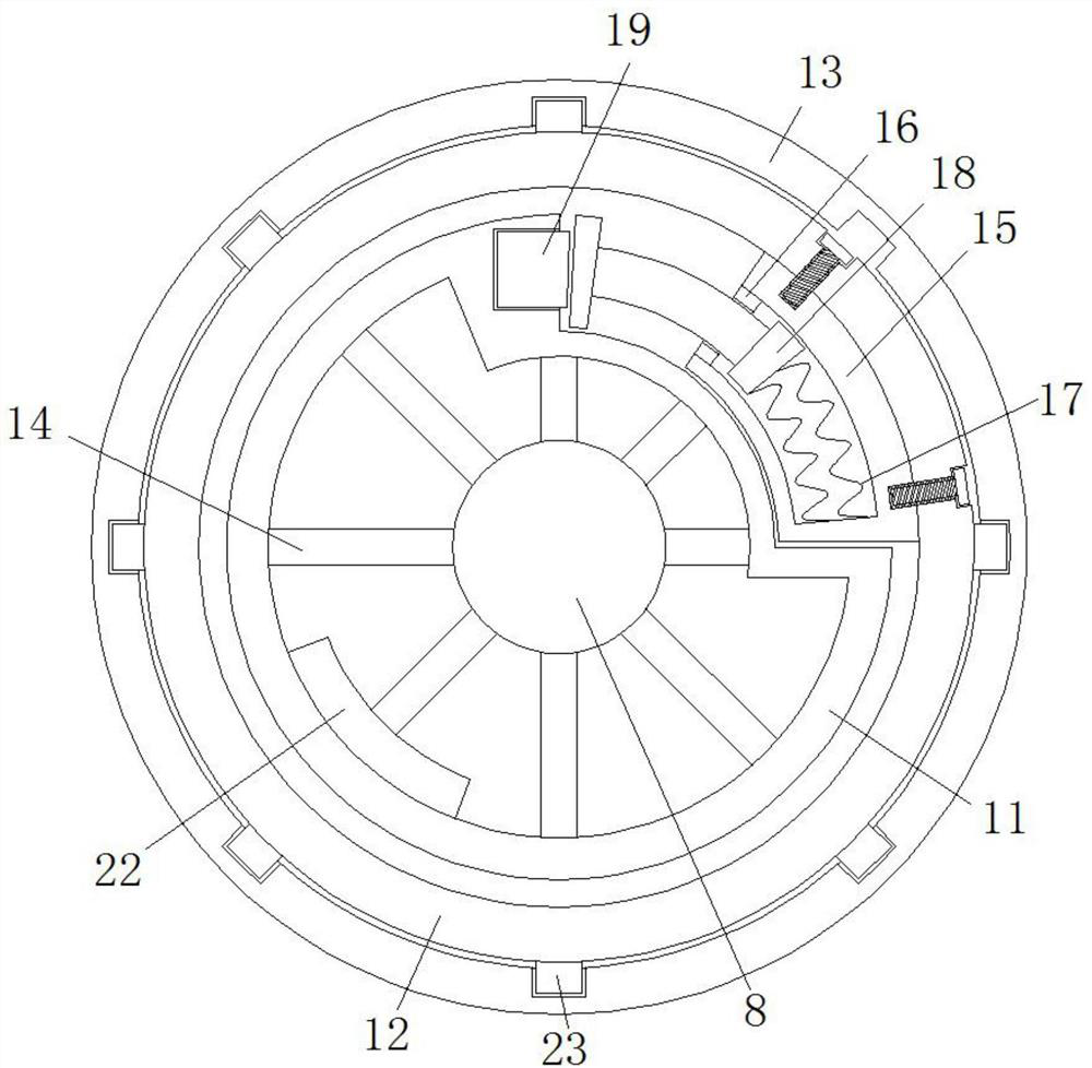
[0022] refer to Figure 1-3 , comprising a track base 1, the top of the track base 1 is provided with a track groove, the top side of the track base 1 is provided with a track plate one 2 and a track plate two 3, the track plate one 2 and the track plate two 3 are arranged side by side, and the track plate one 2 and the track plate two 3 are provided with a fixed pin 5, one side of the track base 1 is fixed with a reciprocating cylinder 6 by bolts, the reciprocating cylinder 6 is horizontally arranged, and the output rod of the reciprocating cylinder 6 is connected to one side of the track plate one 2 Fixedly connected, the top sides of track plate 1 2 and track plate 2 3 are connected with a rotating seat 7, and a rotating seat 7 is connected with a connecting rod 8, and the other rotating seat 7 is connected with an I-shaped rotating seat 7. Part 9, one end of the connecting rod 8 extends to one side of the rotating seat 7 and is fixedly connected with a rotating gear plate ...

Embodiment 2

[0025] Such as Figure 1-3 As shown, this embodiment is basically the same as Embodiment 1. Preferably, several fixing rods 14 are fixedly welded between the connecting rod 8 and the inner cylinder 11, and the fixing rods 14 are arranged divergently.

[0026] In this embodiment, the connecting rod 14 is used to prevent the diameter of the connecting rod 8 from being too large, thereby reducing weight and saving energy.

Embodiment 3

[0028] Such as Figure 1-3 As shown, this embodiment is basically the same as Embodiment 1. Preferably, a weight plate 22 is fixedly connected to the inner wall of the outer cylinder 12 away from the groove.

[0029] In this embodiment, the masses on both sides of the connecting rod 8 are similar, and the rotation is more stable.


PUM


Abstract

The invention discloses a metal wire winding device. The metal wire winding device comprises a track base, and the track base is provided with parallel track grooves; a first track plate and a secondtrack plate are arranged on the top side of the track base and arranged side by side, and a fixing pin is arranged between the first track plate and the second track plate; a reciprocating air cylinder is fixedly installed on one side of the track base through a bolt and horizontally arranged, and an output rod of the reciprocating air cylinder is fixedly connected with one side of the first trackplate; and rotating fixed bases are connected to the top sides of the first track plate and the second track plate correspondingly, and a connecting rod and an I-shaped rotating part are rotatably connected to the interior of each rotating fixed base. According to the metal wire winding device, the wire breaking phenomenon is avoided while the winding efficiency is guaranteed, orderly and continuous conduction of wire winding is guaranteed, the production efficiency is improved, the labor force is saved, wire winding is more uniform, and the using requirements of people in production and lifeare met.

Description

technical field [0001] The invention relates to the field of electromechanical technology, in particular to a metal wire winding device. Background technique [0002] In the production process of the existing metal wire, the finished metal wire after wire drawing needs to be wound on the outside of the reel. The existing winding devices are all driven by the motor to the outside of the reel. , and the rotation speed of the motor is usually set according to the output speed of the production equipment, the rotation speed is basically constant, but in the process of long-term use, the output speed of the production equipment will change, which also requires frequent manual adjustments The speed of the motor, when there is a pause, people also need to manually turn off the motor, often when it can be adjusted or closed not in time, resulting in the phenomenon of line collapse or disconnection, which reduces production efficiency and brings great harm to people's production Big...

Claims


Application Information

Patent Timeline
Patent Type & Authority Patents(China)
IPC IPC(8): B65H59/40B65H65/00B65H59/38B65H54/28B65H54/553
CPCB65H54/283B65H54/553B65H59/385B65H59/40B65H65/00B65H2701/36
Inventor 卢业传
Owner 天长市恒鑫机电设备有限公司
Learn More