Damping device

A vibration-damping device, a technology for connecting position, applied in the direction of lifting device, accumulator device, fluid pressure actuating device, etc., can solve problems such as unfavorable unloading shock, and achieve the effect of opening and closing vibration reduction and mitigation

Active Publication Date: 2013-12-04
ROBERT BOSCH GMBH
View PDF7 Cites 7 Cited by
  • Summary
  • Abstract
  • Description
  • Claims
  • Application Information

AI Technical Summary

Problems solved by technology

[0004] If, when the damping is activated by opening the main valve, the pressure of the previously loaded hydraulic accumulator is higher than the pressure in the pressure ch

Method used


Image

  • Damping device
  • Damping device
  • Damping device

Examples


Embodiment Construction

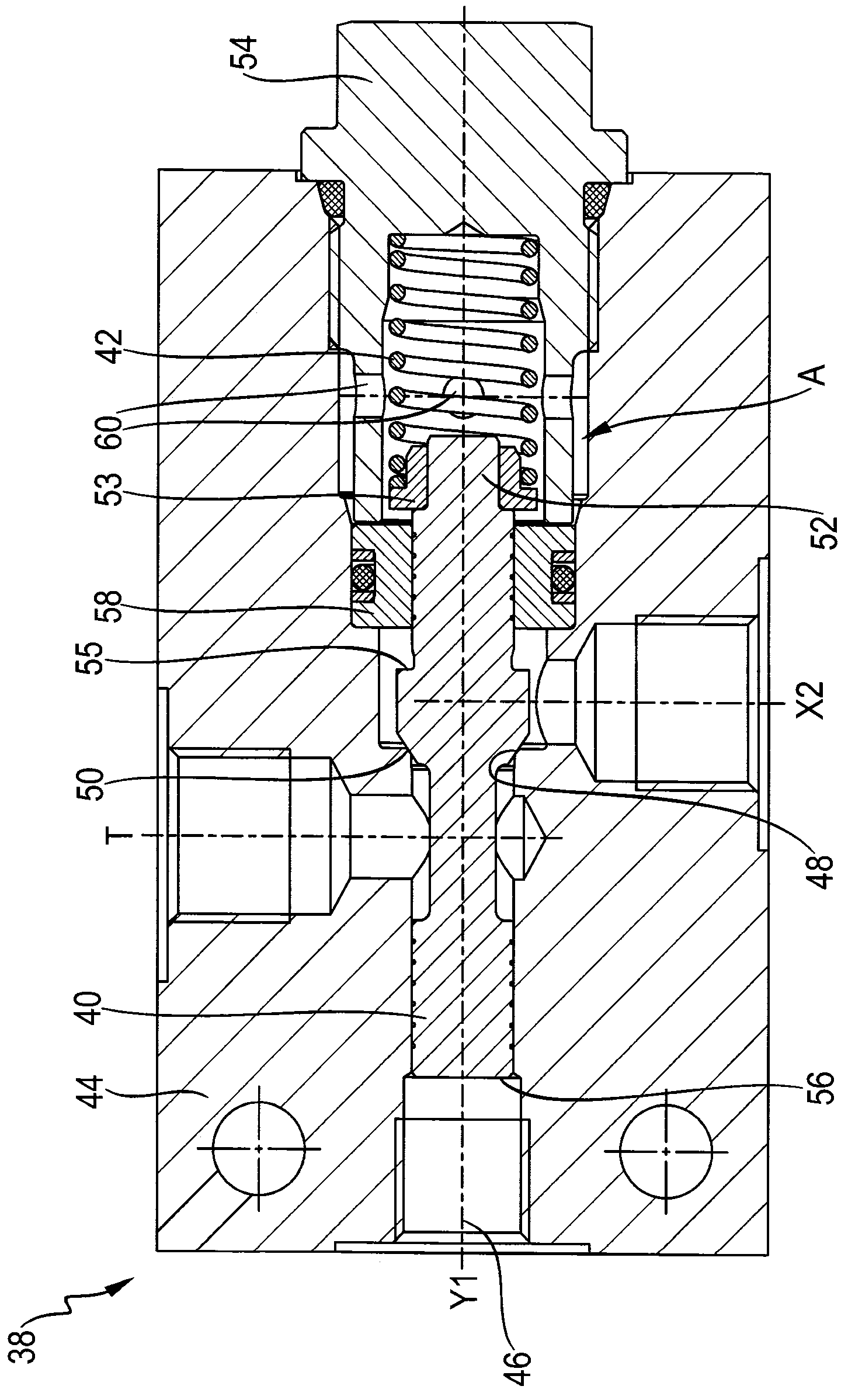
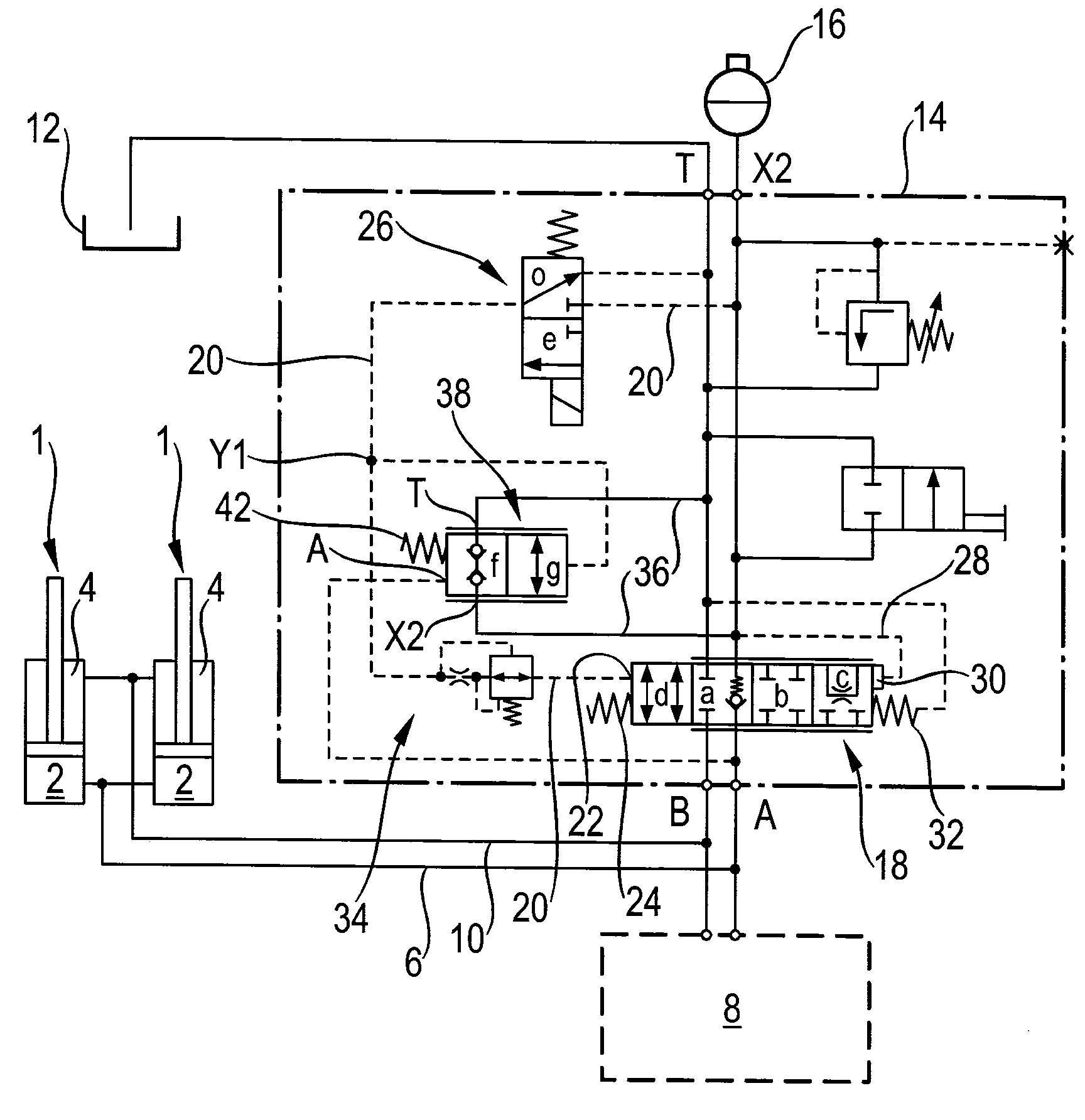
[0079] figure 1 A portion of the hydraulic circuit of a wheel loader is shown. It has two cooperating lifting cylinders 1 which are each designed as a differential cylinder and are used to lift the (not shown) shovel of the wheel loader. The lifting cylinder 1 has a bottom chamber 2 and an annular chamber 4 respectively, wherein the two bottom chambers 2 communicate with the control block 8 of the wheel loader via the first working line 6 and the two annular chambers 4 via the second working line 10 connect. This control block controls the supply of pressure medium to the two lifting cylinders 1 and thus controls the lifting movement of the shovel. Furthermore, the wheel loader has a storage box 12 .

[0080] Especially in the case of relatively rapid travel of the wheel loader (for example above 6 km / h) and especially when the shovel is filled, the hydraulic accumulator 16 can be connected via the vibration damping device 14 according to the invention to the following On ...


PUM


Abstract

A damping device comprises a first working interface for connecting to a load of a working machine, and an accumulator interface for connecting to a hydraulic accumulator. A main valve with at least a first switching position and a second switching position is provided. In the first switching position, a connection from the first working interface to the accumulator interface is opened, so that the attenuation is disabled. In the second switching position, the connection is opened in both directions, so that the attenuation is turned on. Further, a control valve is provided, by which the main valve can be switched hydraulically to the second switching position, and the attenuation can be turned on and off again. The damping device has a discharge valve, which is connected to the control valve, the first working interface and the accumulator interface in such a manner that after the operation of the control valve, the hydraulic accumulator can be partially discharged by the discharge valve when the pressure at the accumulator interface is greater than that at the first working interface. The pressure is discharged or reduced in such a manner that the discharge valve opens a connection from the accumulator interface to a discharge port or a tank interface of the damping device.

Description

technical field [0001] The invention relates to a vibration damping device according to the preamble of claim 1 . Background technique [0002] Such a damper is used, for example, in wheel loaders as a stabilization module to dampen pitching vibrations that occur when driving. For this purpose, the loaded shovel is first lifted by the pump and by the lift cylinder, the pressure chamber of which is under load pressure and is separated from the pump via a control valve. During the loading travel of the wheel loader, the pressure chamber under the load pressure is connected to the loaded hydraulic accumulator via the stabilization module in order to dampen pitching vibrations. [0003] Such a damping device is known from patent document EP 1 407 086 B1, which has a main valve (referred to as a regulating valve (Regelventil)) via which the The connection between the pressure chamber of the lifting cylinder and the hydraulic accumulator is controlled. Via the regulating valve,...

Claims


Application Information

Patent Timeline
IPC IPC(8): E02F9/22
CPCE02F9/2217E02F9/2267E02F9/22E02F9/2207F15B1/021F15B1/033B66F9/22E02F3/42
Inventor K.克鲁格-库休斯E.卡尔E.哈尼施费格J.凯尔
Owner ROBERT BOSCH GMBH
Why Eureka
Try Eureka