
TR (Transverse Rotation) tomography scan projection rearrangement method and device

A technology of tomographic scanning and projection, which is applied in the direction of measuring devices, analyzing materials, and using wave/particle radiation for material analysis, etc. It can solve the problem of inaccurate reconstruction results and other problems

Active Publication Date: 2019-07-26
BEIHANG UNIV
View PDF3 Cites 6 Cited by
  • Summary
  • Abstract
  • Description
  • Claims
  • Application Information

AI Technical Summary

Problems solved by technology

[0006] In order to overcome the problem of inaccurate reconstruction results caused by the above existing rearrangement methods or at least partially solve the above problems, embodiments of the present invention provide a TR tomographic projection rearrangement method and device

Method used


Image

  • TR (Transverse Rotation) tomography scan projection rearrangement method and device
  • TR (Transverse Rotation) tomography scan projection rearrangement method and device
  • TR (Transverse Rotation) tomography scan projection rearrangement method and device

Examples


Embodiment Construction

[0035] In order to more clearly illustrate the technical solutions in the embodiments of the present invention or the prior art, the following will briefly introduce the drawings that need to be used in the description of the embodiments or the prior art. Obviously, the accompanying drawings in the following description These are some embodiments of the present invention. Those skilled in the art can also obtain other drawings based on these drawings without creative work.

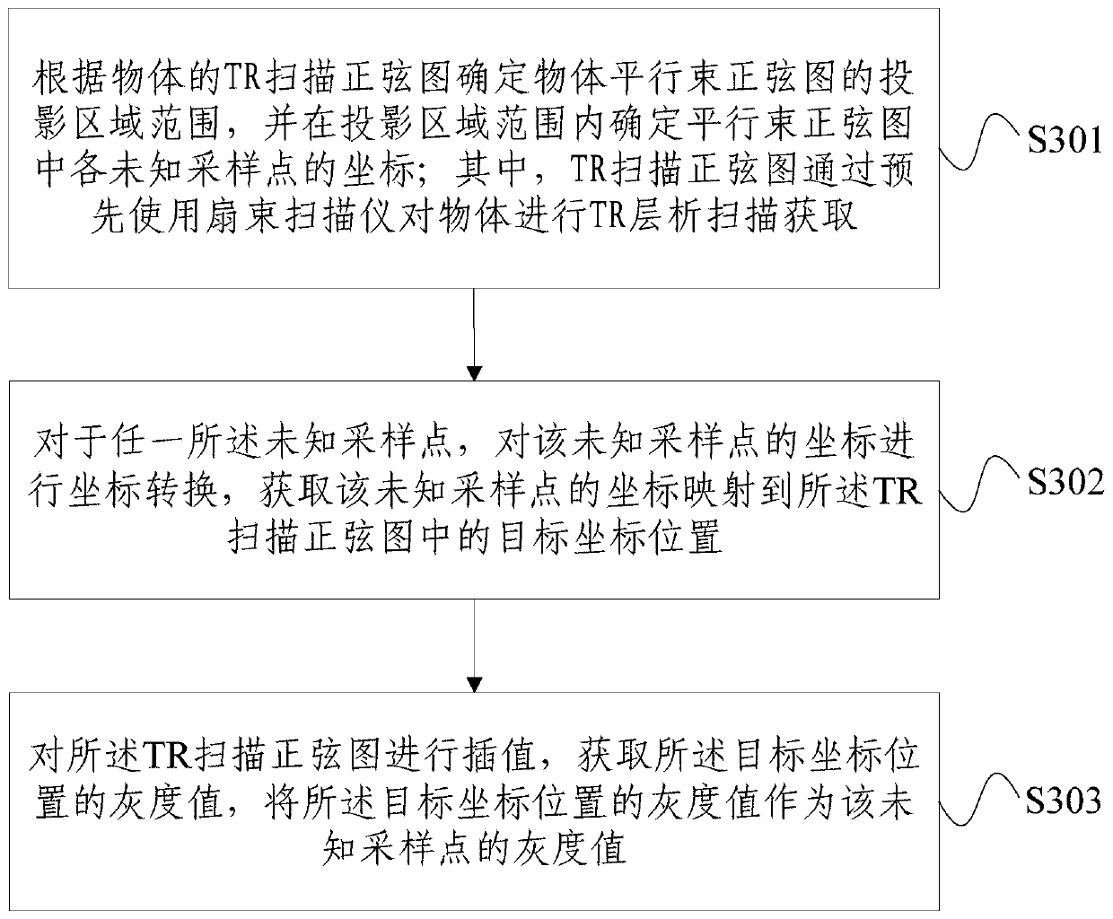
[0036]In one embodiment of the present invention, a TR tomographic projection rearrangement method is provided, image 3 It is a schematic diagram of the overall process flow of the TR tomographic projection rearrangement method provided by the embodiment of the present invention, the method includes: S301, according to the TR scan sinogram of the object, determine the projection area range of the parallel beam sinogram of the object, and in the Determine the coordinates of each unknown sampling point in t...


PUM


Abstract

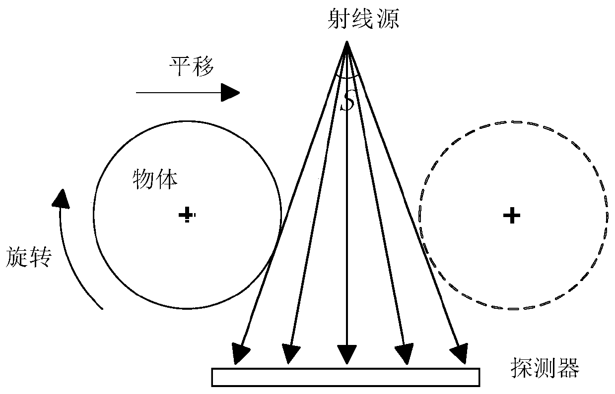
The invention provides a TR (Transverse Rotation) tomography scan projection rearrangement method and device. The method comprises the steps of determining a projection region range of a parallel beamsinogram of an object according to a TR scan sinogram of the object and determining a coordinate of each unknown sample point in the parallel beam sinogram within the projection region range, whereinthe TR scan sonogram is obtained by scanning the object through utilization of a fan beam scanner; for any unknown sample point, carrying out coordinate conversion on the coordinate of the unknown sample point and mapping the obtained coordinate of the unknown sample point to a target coordinate position in the TR scan sinogram; and interpolating the TR scan sonogram, obtaining a gray value of the target coordinate position, and taking the gray value of the target coordinate position as the gray value of the unknown sample point. According to the method and the device, the parallel beam sonogram obtained through conversion according to the TR scan sinogram is relatively accurate, a sectional image obtained through CT reconstruction based on the parallel beam sonogram is smooth in edge, anartifact phenomenon is avoided, and accurate image reconstruction can be realized when a fan beam angle is relatively large.

Description

technical field [0001] The invention belongs to the technical field of CT, and in particular relates to a method and a device for rearranging projections of TR tomographic scanning. Background technique [0002] In recent years, CT (Computed Tomography, electronic computer tomography) detection technology has developed rapidly. Auxiliary manufacturing) and other manufacturing technologies are combined to form reverse engineering. These advantages are not available in other non-destructive testing techniques. The detection image obtained by X-ray CT imaging detection technology is a two-dimensional tomographic image corresponding to the characteristics of the workpiece material, structure, composition and density, and there is no problem of information superposition. The detection image is the result of digitization, from which physical information such as CT value and pixel size can be directly obtained. [0003] However, the detected object often has great uncertainty in...

Claims


Application Information

Patent Timeline
IPC IPC(8): G01N23/046
CPCG01N23/046
Inventor 杨民孙亮宋鑫林强吴雅朋
Owner BEIHANG UNIV
Learn More