Method for medical imaging

a medical imaging and image technology, applied in the field of medical imaging, can solve the problems of difficult navigation using these 2d images, high patient stress, and relatively high continuous radiation image recording during intervention

Active Publication Date: 2009-01-06
SIEMENS HEALTHCARE GMBH
View PDF18 Cites 37 Cited by
  • Summary
  • Abstract
  • Description
  • Claims
  • Application Information

AI Technical Summary

Benefits of technology

[0004]An object of the invention is therefore to set down a method which makes possible an informative image presentation of the catheter whilst simultaneously subjecting the patient to minimum radiation exposure.
[0014]When both the coordinate systems and thus the data sets have been registered, the only further action required is to acquire the current ECG data which is exclusively responsible for triggering the 3D reconstruction image presentation. As a result of the coordinate system registration and also of the association with the ECG data, it is possible by using the current ECG data to precisely reconstruct at any time the particular 3D presentation which, in relation to phase and time, and as a result of the coordinate system registration also in relation to location, reflects the current form of the investigation region even though it does not involve current image data but data recorded preoperatively. This serves to ensure that with a minimum radiation dosage it is possible to produce a three-dimensional presentation of the heart which is correct in relation to phase, time and location, simply on the basis of current ECG data.
[0016]In total, the method according to the invention allows a continuous presentation of the moving examination area whilst subjecting the patient to only minimal radiation exposure and simultaneously presenting the instrument with accuracy of location in the 3D volume.
[0017]Basically it is not necessary once the registration of the 2D fluoroscopic image with the 3D image data set has taken place at the beginning to record further 2D fluoroscopic images, even though this can sometimes be advantageous at times when there is a danger of the patient moving or being moved and therefore changing the current position of the examination region, even if only slightly. In order to acquire such changes, an advantageous development of the invention makes provision whereby further 2D fluoroscopic images and the associated ECG data are intermittently recorded, and these are used for the checking the registration and the correct positional presentation of the 3D reconstruction image, and making corrections where necessary. In other words, a 2D control image is recorded from time to time, depending on which the given registration situation is checked. If the analysis yields the result that the mapping parameters found within the scope of the registration are still applicable as before, in other words the examination region has not therefore changed in respect of its location, there is no need for any correction, otherwise the analysis yields a mismatch. A renewed registration procedure serves to determine a corrected mapping specification which is subsequently used as the basis for the entire further 3D image reconstruction and the corresponding presentation on the monitor and also for superimposing the instrument in the volume. The intermittent radiation images can be recorded for example at one minute intervals, or every three or five minutes. The final time interval depends on the overall duration of the intervention. The recording time interval can advantageously be set on the user side and can thus be tailored to the current situation, and can if necessary also be changed during execution of the method according to the invention, depending on requirements.

Problems solved by technology

The navigation using these 2D images is difficult on account of the lack of depth information or spatial information, and in addition the stress on the patient as a result of the continuous radiation image recording during the intervention is relatively high.

Method used


Image

  • Method for medical imaging
  • Method for medical imaging

Examples


Embodiment Construction

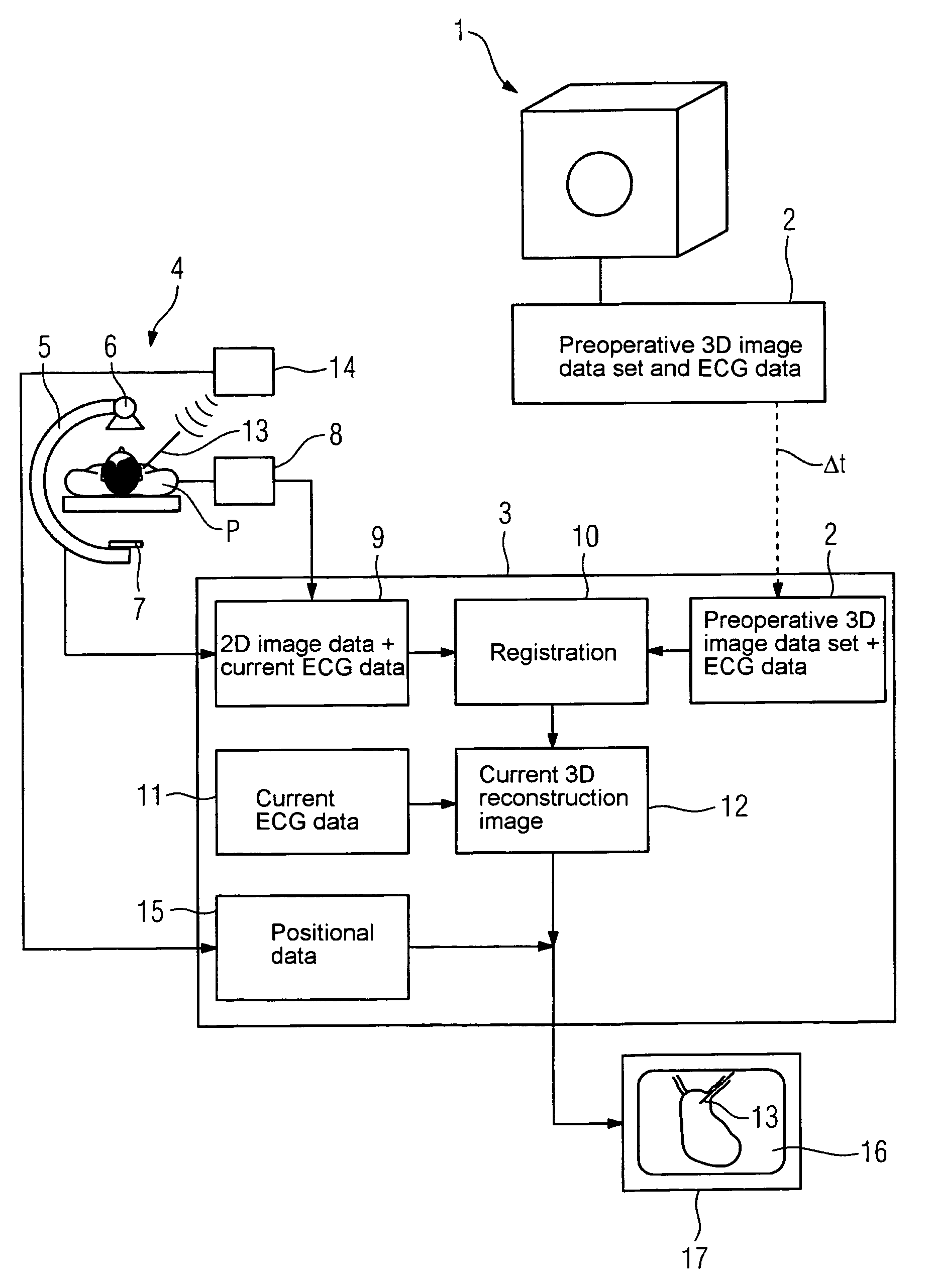
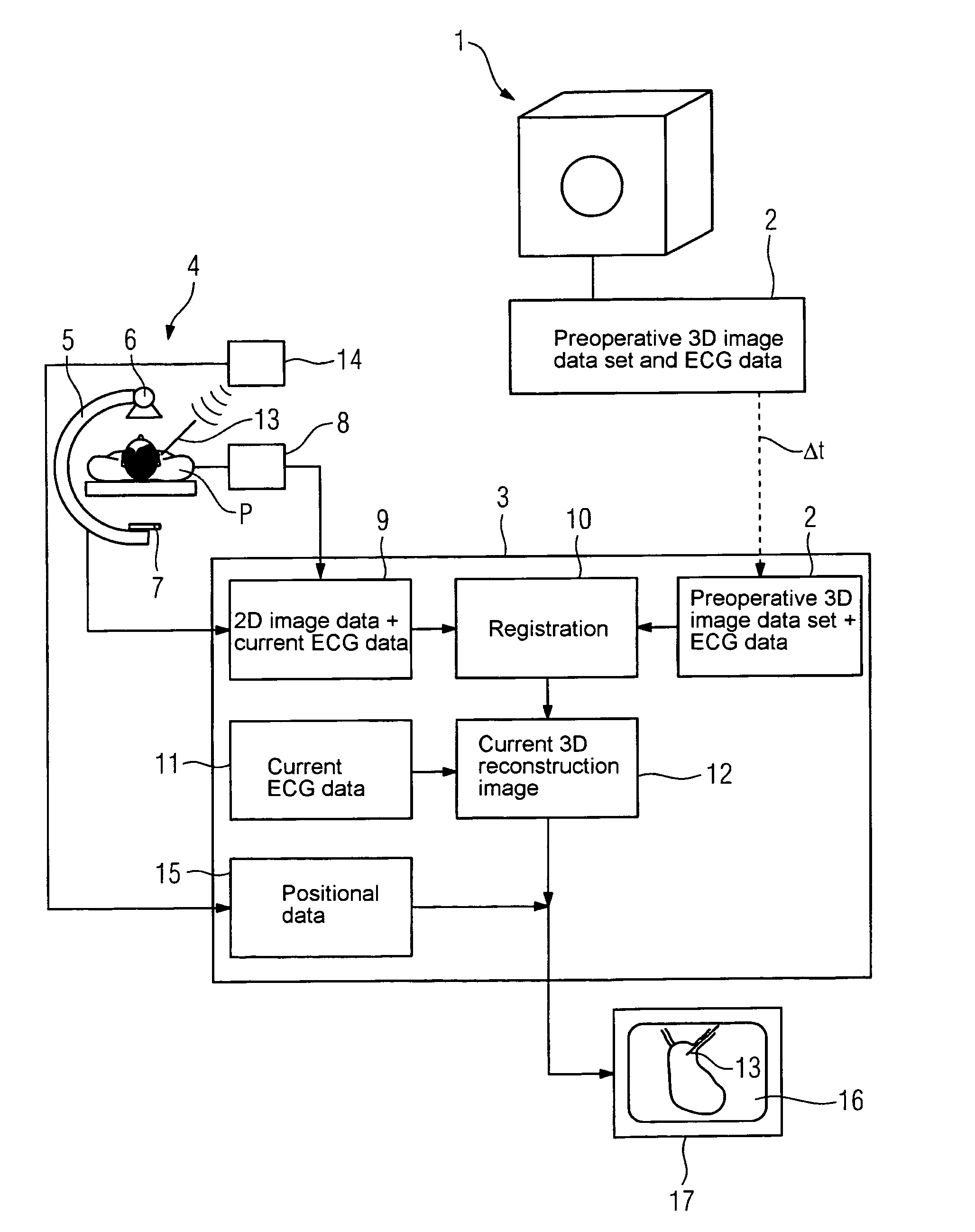
[0019]The drawing on the one hand shows a first mode of examination 1, a magnetic resonance imaging machine in the example illustrated, which is used for recording a preoperative 3D image data set along with the associated ECG data which are derived from an acquisition unit not shown in detail, which is represented in the field labeled 2.

[0020]This preoperative 3D image data set and the associated ECG data are passed at some later point in time (Δt) to a control and processing unit 3 of a medical examination device 4 according to the invention, here taking the form of a C-arm X-ray device 5 where they are stored. The C-arm X-ray device 5 comprises a radiation source 6 and a radiation detector 7 in the known manner, which is used for recording a 2D fluoroscopic image. This image data is likewise passed to the control unit 3. The ECG is acquired in parallel to the 2D image recording by way of an ECG acquisition unit 8. The ECG data is then associated with the 2D image data or rather t...


PUM


Abstract

A method for medical imaging is provided, wherein a current position of a medical instrument inserted into a moving examination area of a patient is displayed. The medical instrument is displayed within a reconstructed three-dimensional image of the moving examination area based on position data of the instrument registered with a coordinate system of the reconstructed three-dimensional image. The reconstructed three-dimensional image is a simulation of the moving examination area using a pre-insertion 3D image of the examination area correlated with pre-insertion ECG data of the patient. A display of the reconstructed three-dimensional image is triggered by current ECG data of the patient.

Description

CROSS REFERENCE TO RELATED APPLICATIONS[0001]This application claims priority to the German application 10 2004 030 836.5, filed Jun. 25, 2004 which is incorporated by reference herein in its entirety.FIELD OF INVENTION[0002]The invention relates to a method for image presentation of a medical instrument introduced into a rhythmically or arrhythmically moving examination region of a patient, in particular a catheter.BACKGROUND OF INVENTION[0003]Within the scope of minimally invasive intervention actions, in which for example catheters are inserted into hollow spaces, the coronary blood vessels for example, the optical presentation of the moving instrument plays a central role in relation to the examination region in enabling the physician to navigate the instrument which is no longer visible to him after introducing it into the patient. To this end, a method is known whereby an X-ray fluoroscopy device is used to continuously record and output two-dimensional X-ray images which the ...

Claims


Application Information

Patent Timeline
Patent Type & Authority Patents(United States)
IPC IPC(8): A61B6/00A61B6/12
CPCA61B6/12A61B6/504A61B6/5235A61B5/7285A61B6/503A61B6/5247A61B6/541
Inventor DURLAK, PETER
Owner SIEMENS HEALTHCARE GMBH
Why Eureka
Try Eureka