Super-resolution imaging system based on compression coding aperture and imaging method thereof

A compression coding and super-resolution technology, applied in the parts of TV system, image communication, color TV, etc., can solve the problems of expensive CCD, dynamic range, sensitivity reduction, pixel size reduction, etc.

Inactive Publication Date: 2012-05-02
XIDIAN UNIV
View PDF3 Cites 37 Cited by
  • Summary
  • Abstract
  • Description
  • Claims
  • Application Information

AI Technical Summary

Problems solved by technology

There are two shortcomings in this traditional imaging method: First, due to the high sampling rate, the resolution requirements of the CCD are relatively high
On the premise that other parameters are determined, high-resolution CCDs are more expensive than low-resolution CCDs
Moreover, the improvement of CCD resolution will lead to the reduction of pixel size, which will lead to the reduction of imaging performance, such as dynamic range and sensitivity.
The second is to collect a large amount of data first, and then compress the data is a waste of resources
Therefore, if the scene changes from time to time, the effect obtained by this method will be poor

Method used


Image

  • Super-resolution imaging system based on compression coding aperture and imaging method thereof
  • Super-resolution imaging system based on compression coding aperture and imaging method thereof
  • Super-resolution imaging system based on compression coding aperture and imaging method thereof

Examples


Embodiment 1

[0074] Embodiment 1: measuring method of the present invention comprises the steps:

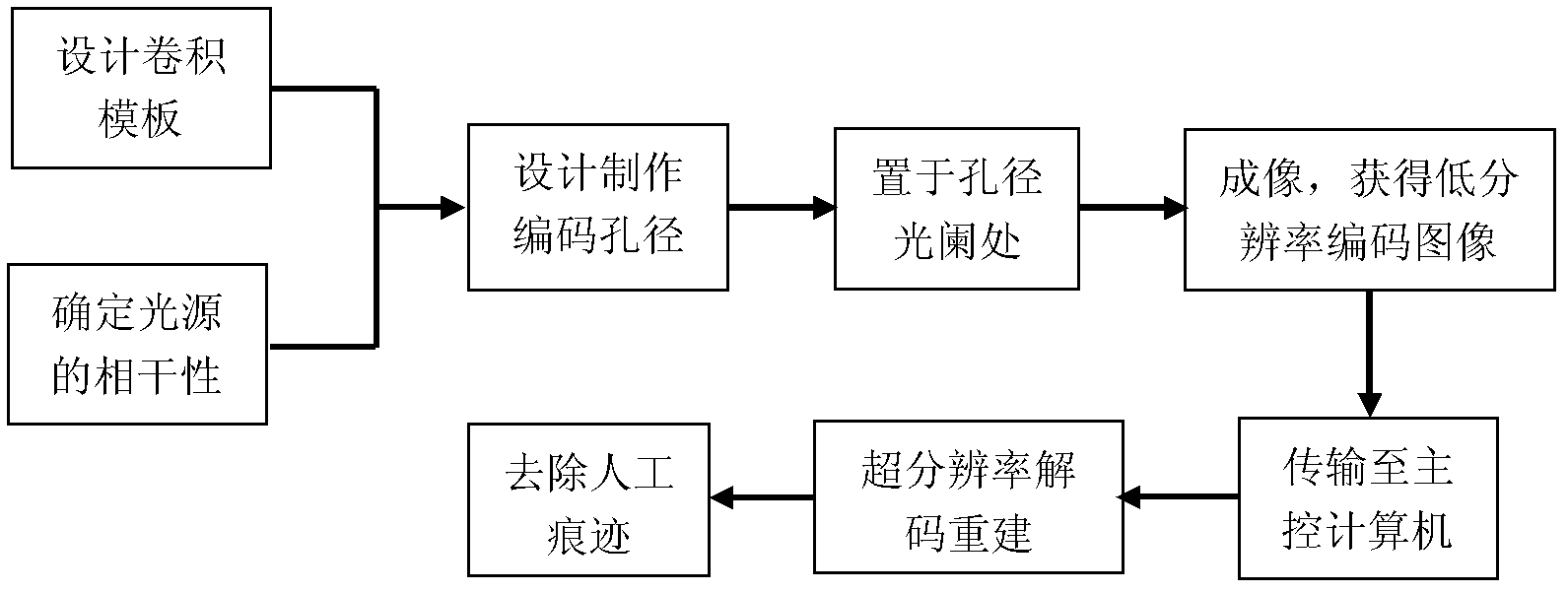
[0075] Step 1, design the convolution template H corresponding to the coding aperture.

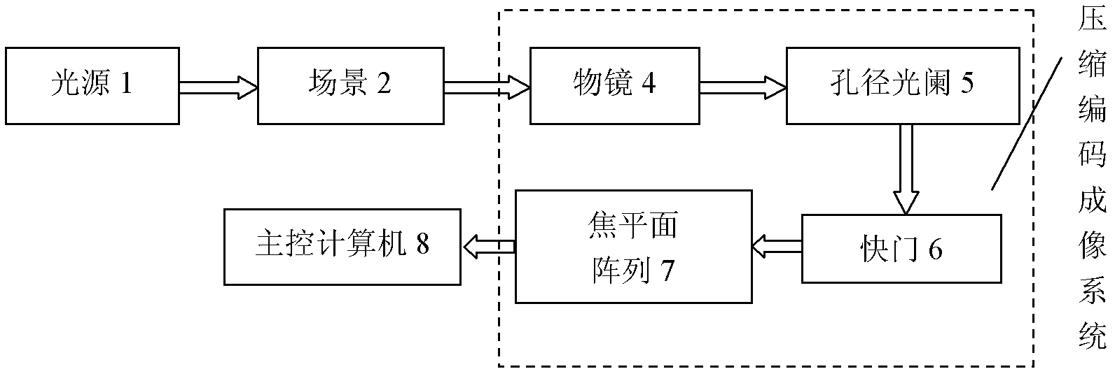
[0076] When the optical signal passes through the linear invariant system, the output optical signal X out Can be regarded as the input optical signal X in Convolution result with convolution template H, ie F out =F in *H, where the convolution template H is only related to the imaging system. In this imaging system, the convolution template H is determined by the coded aperture template P in the system. The specific steps are as follows:

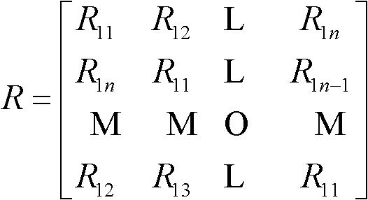
[0077] 1.1) In order to obtain a better coding effect, the size of the convolution template matrix H is determined by the resolution of the desired high-resolution image. When the resolution of the high-resolution image is n×n, the convolution template matrix H The size of is set to n×n dimensions, and the encoding effect at this time is the best;

[0078] 1.2) Co...

Embodiment 2

[0110] Embodiment 2: measuring method of the present invention comprises the steps:

[0111] Step A, design the convolution template H corresponding to the coding aperture.

[0112] When the optical signal passes through the linear invariant system, the output optical signal X out Can be regarded as the input optical signal X in Convolution result with convolution template H, ie F out =F in *H, where the convolution template H is only related to the imaging system. In this imaging system, the convolution template H is determined by the coded aperture template P in the system. The specific steps are as follows:

[0113] A1) In order to obtain a better coding effect, the size of the convolution template matrix H is determined by the resolution of the desired high-resolution image. When the resolution of the high-resolution image is n×n, the convolution template matrix H The size of is set to n×n dimensions, and the encoding effect at this time is the best;

[0114] A2) Conv...


PUM


Abstract

The invention discloses a super-resolution imaging system based on a compression coding aperture and an imaging method thereof, mainly solving a problem of expensive imaging cost in the prior art. The method comprises the following steps: designing a convolution template, and making a coding aperture according to coherence of a light source; placing the prepared coding aperture at a position of aperture diaphragm in an optical system and pressing a shutter for imaging, and obtaining a low resolution coding image; transmitting the coding image to a master control computer, decoding super-resolution to reconstruct a high-resolution image, and using a denoising algorithm to remove an artificial trace in the high-resolution image. The system and the method are characterized in that: restriction of a Nyquist criterion is broken through, low frequency sampling is carried out on a scene, the high-resolution image is obtained through super-resolution reconstruction, data waste caused by first sampling and second compression of a traditional imaging system is overcome, in sampling, data volume is compressed, imaging cost, compression cost and transmission cost are reduced, and the system and the method can be used for infrared imaging and remote sensing imaging technology.

Description

technical field [0001] The invention belongs to the technical field of image processing and imaging, relates to an optical system and image reconstruction, and is mainly used for optical super-resolution imaging. Background technique [0002] The traditional optical imaging method collects data through the front-end optical system and the back-end charge-coupled device CCD. The sampling frequency conforms to the Nyquist sampling theorem, which means that the spatial interval of CCD pixels should not be greater than half of the size of the details concerned. Due to the huge amount of collected data, it is generally necessary to compress the collected data for easy storage and transmission. There are two shortcomings in this traditional imaging method: First, due to the high sampling rate, the resolution requirements of the CCD are relatively high. On the premise that other parameters are determined, high-resolution CCDs are more expensive than low-resolution CCDs. Moreover,...

Claims


Application Information

Patent Timeline
Patent Type & Authority Applications(China)
IPC IPC(8): H04N5/232H04N5/235H04N7/26H04N19/87
Inventor 邵晓鹏钟宬靳振华范华黄远辉卢光旭徐大雍马菁汀饶存存侯谨妍乔琳
Owner XIDIAN UNIV
Why Eureka
Try Eureka