
Digital images and related methodologies

a digital image and image technology, applied in the field of digital images, can solve the problems of compromising image resolution and contrast for magnification, not realizing the best physically possible, and rarely, if ever actually, achieving the resolution of such an optical system in practice, so as to achieve the effect of increasing the signal-to-noise ratio

Active Publication Date: 2004-11-18
PIXEL MATCHED HLDG
View PDF39 Cites 38 Cited by
  • Summary
  • Abstract
  • Description
  • Claims
  • Application Information

AI Technical Summary

Benefits of technology

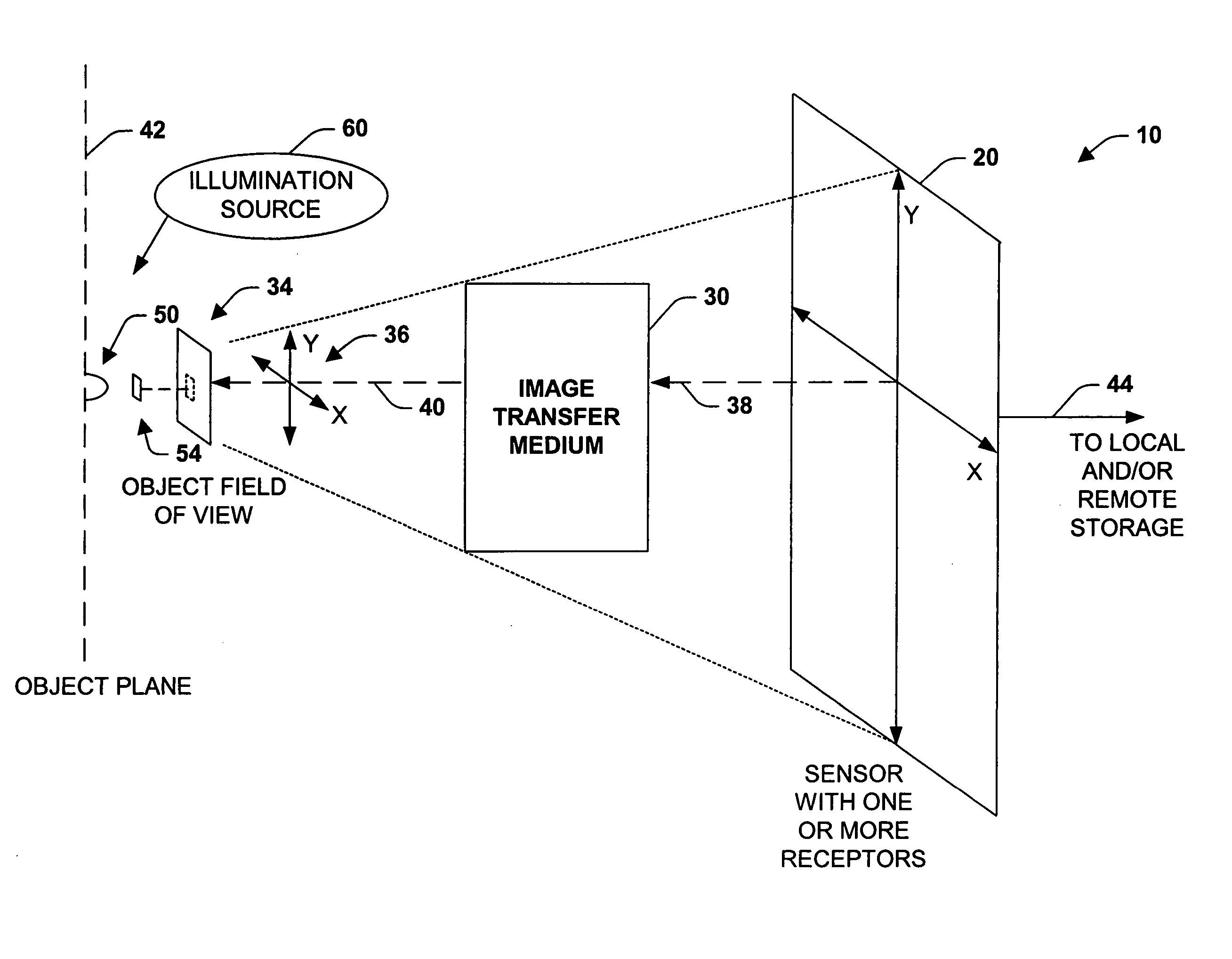
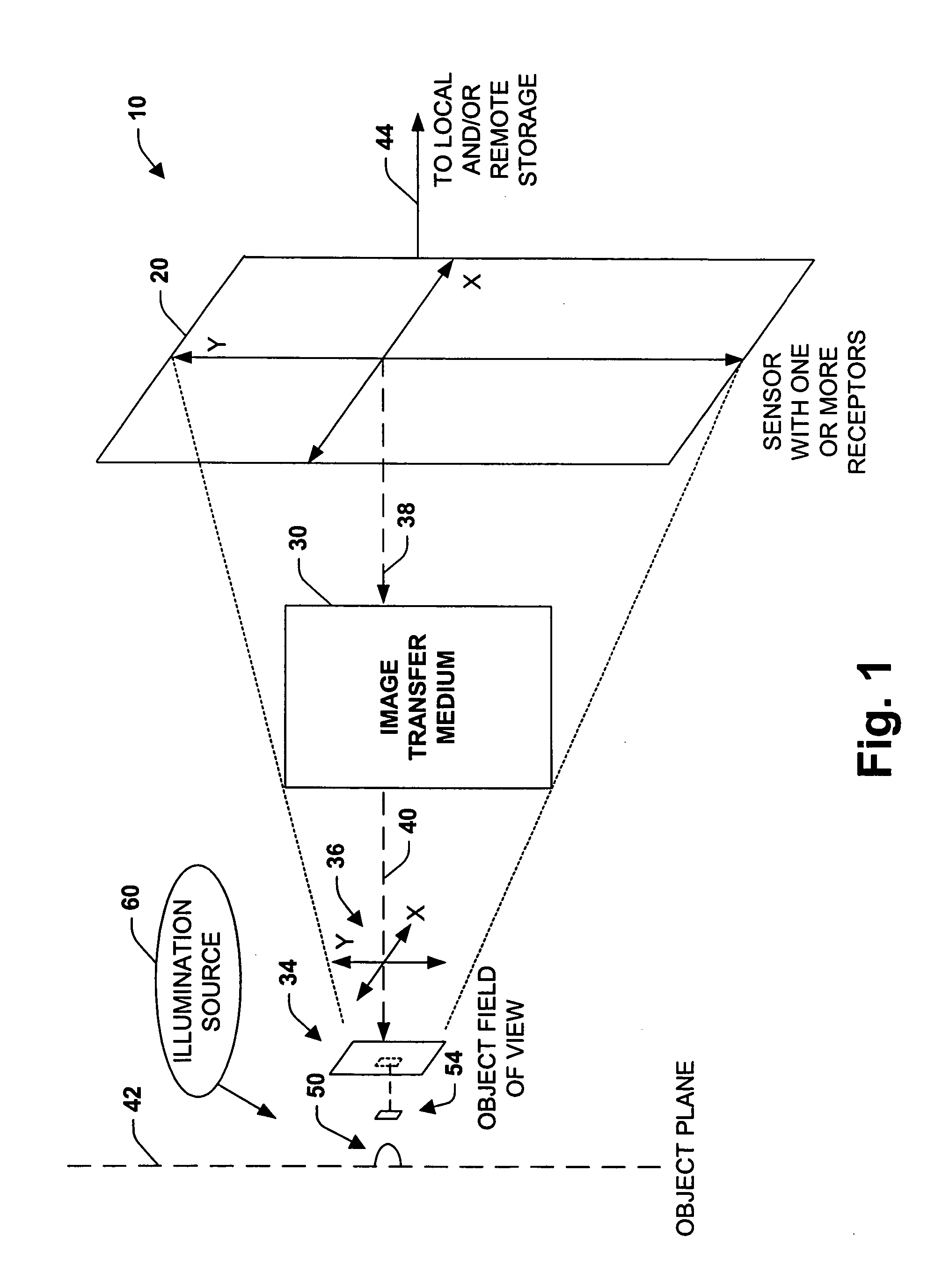
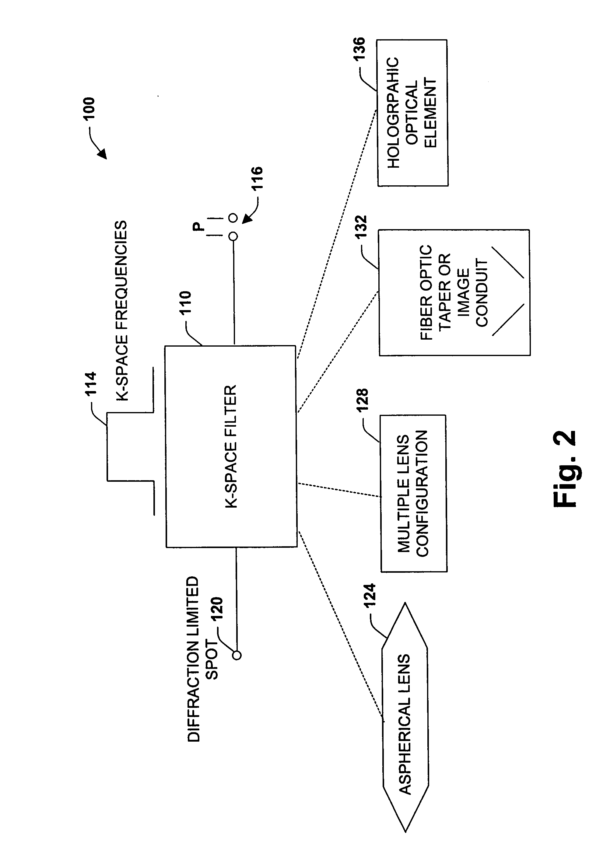
[0007] The imaging systems of the present invention is specifically designed to present object data to a digital imaging device (such as a CCD or CMOS camera) and uses resolution as the primary design parameter. Matching projected pixel size in the object plane to the diffraction limited spot size in the object plane, in accordance with one or more parameters discussed below, provides the systems of the present invention with at least one of: gain in information retrieval, gain in removing indeterminacy (or mitigation of indeterminacy), gain in brightness per pixel, and gain in edge-sharpness compared to conventional imaging systems.
[0008] When projected pixel size in the object plane is matched to the diffraction limited spot size (smallest resolvable feature) in the object plane, indeterminacy is mitigated. By mitigating indeterminacy, a more accurate reconstruction of spatial frequencies of interest is achieved compared to conventional imaging systems designed to place at least 2.5 projected pixels into the diffraction limited spot.

Problems solved by technology

The theoretical best resolution of such an optical system can be computed but is rarely, if ever actually, in practice achieved.
Employing digital imaging devices on conventional microscopes further compromises image resolution and contrast for magnification.
In other words, although modern digital imaging microscopes can make very good and "pleasing" images, they do not really achieve the best physically possible.

Method used


Image

  • Digital images and related methodologies
  • Digital images and related methodologies
  • Digital images and related methodologies

Examples


Embodiment Construction

Optical Parameters

[0326]

2 Resolution NA DOF WD Mag 2,500 nm 0.10 100 um 125 mm 1x 1,000 nm 0.25 16 um 48 mm 3x 625 nm 0.40 6.25 um 28 mm 4x 384 nm 0.65 2.40 um 14 mm 7x

Conventional Microscope Optical Parameters

[0327]

3 Mag Req'd for Resolution NA DOF WD resolution (10x eyepiece) 2,500 nm 0.10 100 um 125 mm 100x 1,000 nm 0.25 16 um 48 mm 250x 625 nm 0.40 6.25 um 28 mm 400x 384 nm 0.65 2.40 um 14 mm 650x

[0328] To achieve a resolution of 2,500 nm, the Conventional Microscope requires a 100.times. magnification and thus has a resolution performance of {fraction (1 / 100)} of that of the imaging system of the present invention. To achieve a resolution of 2,500 nm, the Conventional Microscope requires a 100.times. magnification and thus has a, resolution performance of {fraction (1 / 80)} of that of the imaging system of the present invention. To achieve a resolution of 2,500 nm, the Conventional Microscope requires a 100.times. magnification and thus has a resolution performance of {fraction ...


PUM


Abstract

An imaging system, methodology, and various applications are provided to facilitate optical imaging performance. The system contains a sensor having one or more receptors and an image transfer medium to scale the sensor and receptors in accordance with resolvable characteristics of the medium, and as defined with certain ratios. Also provided are digital images that contain a plurality of image pixels, each image pixel containing information from about one sensor pixel, each sensor pixel containing substantially all information from about one associated diffraction limited spot in an object plane. Methods of making digital images are provided.

Description

[0001] This application is continuation-in-part of U.S. patent application of Ser. No. 10 / 758,836 which was filed Jan. 16, 2004 entitled IMAGING SYSTEM AND METHODOLOGY, which is a continuation-in-part of U.S. patent application of Ser. No. 10 / 616,829 which was filed Jul. 10, 2003 entitled IMAGING SYSTEM, METHODOLOGY, AND APPLICATIONS EMPLOYING RECIPROCAL SPACE OPTICAL DESIGN, which is a continuation-in-part of U.S. patent application Ser. No. 10 / 189,326 which was filed Jul. 2, 2002 entitled IMAGING SYSTEM AND METHODOLOGY EMPLOYING RECIPROCAL SPACE OPTICAL DESIGN, which is a continuation-in-part of U.S. patent application Ser. No. 09 / 900,218, which was filed Jul. 6, 2001, entitled IMAGING SYSTEM AND METHODOLOGY EMPLOYING RECIPROCAL SPACE OPTICAL DESIGN now U.S. Pat. No. 6,664,528, all of which are incorporated herein by reference.[0002] The present invention relates generally to image and optical systems, and more particularly to a system and method to facilitate imaging performance ...

Claims


Application Information

Patent Timeline
Patent Type & Authority Applications(United States)
IPC IPC(8): H04N5/225
CPCG01N21/6458G01N21/9501G01N2015/1479G01N2015/1497G02B21/361G06T3/0056G06T3/10
Inventor CARTLIDGE, ANDREW G.FEIN, HOWARD
Owner PIXEL MATCHED HLDG
Learn More