Wiring device

A wiring device and wiring technology, applied in the direction of optical fiber/cable installation, etc., can solve the problems of inconvenient wiring, and achieve the effects of convenient wiring, convenient operation and simple structure

Pending Publication Date: 2019-07-26
GUANGDONG POWER GRID CO LTD +1
View PDF0 Cites 0 Cited by
  • Summary
  • Abstract
  • Description
  • Claims
  • Application Information

AI Technical Summary

Problems solved by technology

[0004] The present invention provides a wiring device for overcoming the

Method used


Image

  • Wiring device
  • Wiring device

Examples


Example Embodiment

[0026] Example 1:

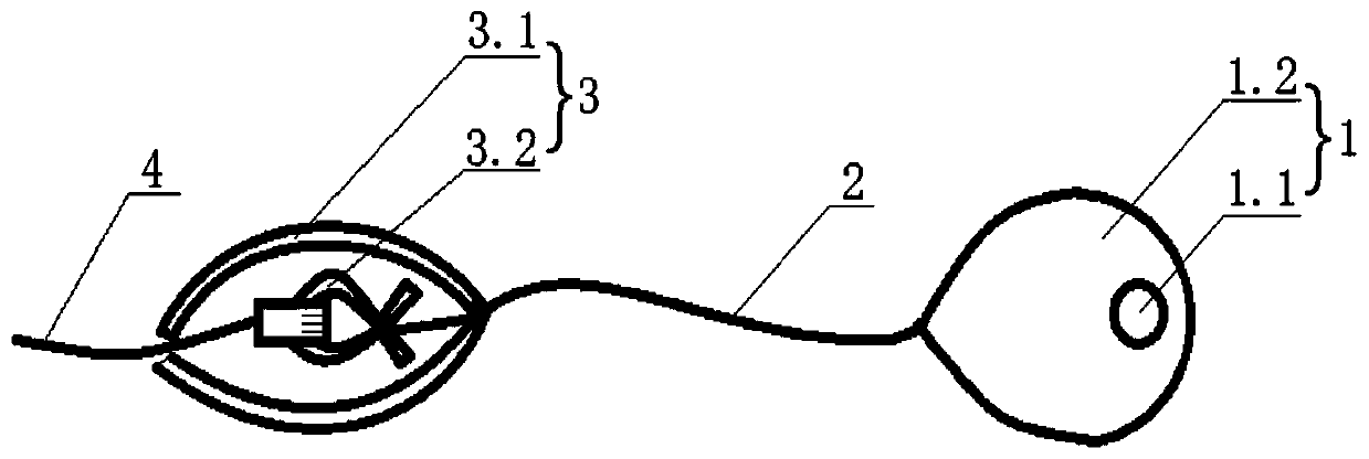
[0027] This embodiment provides a wiring device, such as figure 1 As shown, the device includes a traction rope 2 and a weight block 1. One end of the traction rope 2 is fixedly connected to the weight block 1, and the other end is used to connect the pigtail 4 of the optical fiber to be wired.

[0028] The end of the pulling rope 2 connected with the pigtail of the optical fiber to be wired is provided with a fixing member 3 for fixing the pigtail 4 of the optical fiber to be wired.

[0029] The fixing member 3 includes a rubber sleeve 3.1. The two ends of the rubber sleeve 3.1 are pointed. One end of the rubber sleeve 3.1 is connected to the traction rope 2 and the other end is provided with an opening. The opening can be opened by external force to connect the wiring The pigtail 4 of the optical fiber is fixed in the rubber sleeve 3.1, and the open end of the rubber sleeve 3.1 returns to a pointed shape after the external force is removed.

[0030] The fixing me...

Example Embodiment

[0037] Example 2:

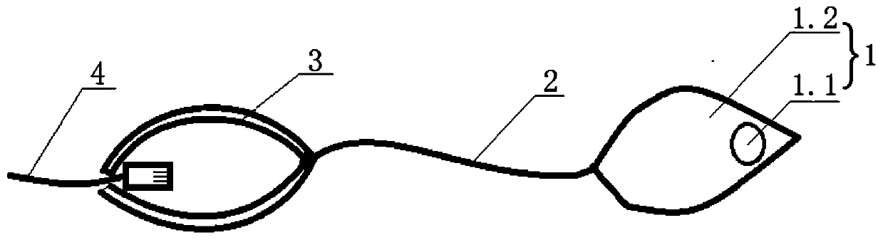
[0038] This embodiment provides a wiring device, such as figure 1 As shown, the device includes a traction rope 2 and a weight block 1. One end of the traction rope 2 is fixedly connected to the weight block 1, and the other end is used to connect the pigtail 4 of the optical fiber to be wired.

[0039] The end of the pulling rope 2 connected with the pigtail of the optical fiber to be wired is provided with a fixing member 3 for fixing the pigtail 4 of the optical fiber to be wired.

[0040] The fixing member 3 is a rubber sleeve. The two ends of the rubber sleeve are pointed. One end of the rubber sleeve is connected with the traction rope 2 and the other end is provided with an opening. The opening can be opened by external force, and the tail of the optical fiber to be wired The fiber 4 is fixed in the rubber sleeve, and the open end of the rubber sleeve returns to a pointed shape after the external force is removed.

[0041] The weight block 1 includes a buffe...


PUM


Abstract

The invention relates to a wiring device comprising a traction rope, a weight block and a fixing member, wherein one end of the traction rope is fixedly connected to the weight block, and the other end is used for connecting the pigtail of the fiber to be wired; one end of the traction rope connected to the pigtail of the fiber to be wired is provided with the fixing member for fixing the pigtailof the fiber to be wired; the fixing member comprises a rubber sleeve and a wire clip, both ends of the rubber sleeve are pointed, one end is provided with an opening that can be opened by an externalforce, and the pigtail of the fiber to be wired is fixed in the rubber sleeve; the weight block comprises a buffering member and a weighting block, and the weighting block is disposed in the buffering member and away from one end of the traction rope; the joint of the buffering member and the traction rope is set as a pointed shape, and the other end is spherical or pointed. The invention has theadvantages of simple structure, convenient operation and low cost. When used, the traction rope is grasped, the soft rubber buffer ball is thrown by parabola through the slot to be spanned, and the traction rope that has been spanned is pulled to tract and span the pigtail, thereby completing a spanning wiring.

Description

technical field [0001] The present invention relates to the field of power communication auxiliary devices, and more specifically, to a wiring device. Background technique [0002] With the rapid development of power communication technology, optical communication equipment has been widely used. Optical fiber communication has many advantages such as large communication capacity, high anti-interference and long transmission distance. [0003] Due to the obstruction of the horizontal rail and the hanging support rod, it is necessary to move the ladder repeatedly, climb up and down, and pass the optical fiber through the cross rail and the hanging support rod. In this case, the wiring is inconvenient, and the wiring work efficiency is extremely low. Contents of the invention [0004] The present invention provides a wiring device to overcome the disadvantage of inconvenient wiring in the prior art. [0005] The device includes a traction rope and a weight block, one end of...

Claims


Application Information

Patent Timeline
IPC IPC(8): G02B6/46
CPCG02B6/46
Inventor 余勇
Owner GUANGDONG POWER GRID CO LTD
Why Eureka
Try Eureka