Positioning and assembling die for ceramic shell of vacuum switch tube

A technology of vacuum switch tube and ceramic shell, which is used in electrical switches, auxiliary devices, manufacturing tools, etc., can solve problems such as errors, damage to the ceramic shell, and inability to hold the cover plate, and achieve the effect of improving welding quality and increasing stability.

Active Publication Date: 2019-07-26
JINHUA MINGZHENG TECH CO LTD
View PDF5 Cites 6 Cited by
  • Summary
  • Abstract
  • Description
  • Claims
  • Application Information

AI Technical Summary

Problems solved by technology

[0004] 1. The existing alignment between the cover plate and the ceramic shell is carried out manually. There is a certain error in the artificial alignment, resulting in poor welding effect of the switch tube, and the cover plate cannot be quickly removed after the alignment is completed. The cover plate is pressed, resulting in the position of the cover plate requiring multiple alignment operations;
[0005] 2. The existing ceramic shell of the switch tube is locked by a three-jaw chuck. When the three-jaw chuck locks it, it is easy to cause damage to the ceramic shell, and the three-jaw chuck cannot fit the ceramic shell when it is locked. shape

Method used


Image

  • Positioning and assembling die for ceramic shell of vacuum switch tube
  • Positioning and assembling die for ceramic shell of vacuum switch tube
  • Positioning and assembling die for ceramic shell of vacuum switch tube

Examples


Embodiment Construction

[0031] In order to make the technical means, creative features, goals and effects achieved by the present invention easy to understand, the present invention will be further described below in conjunction with specific illustrations. It should be noted that, in the case of no conflict, the embodiments in the present application and the features in the embodiments can be combined with each other.

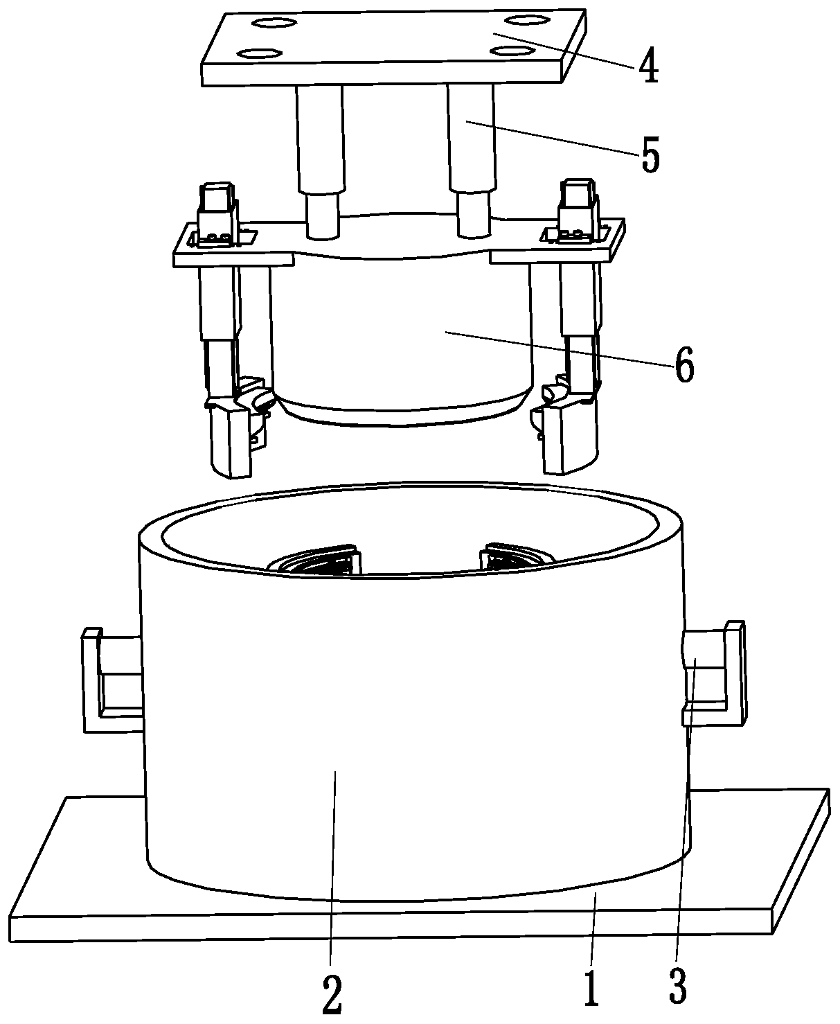
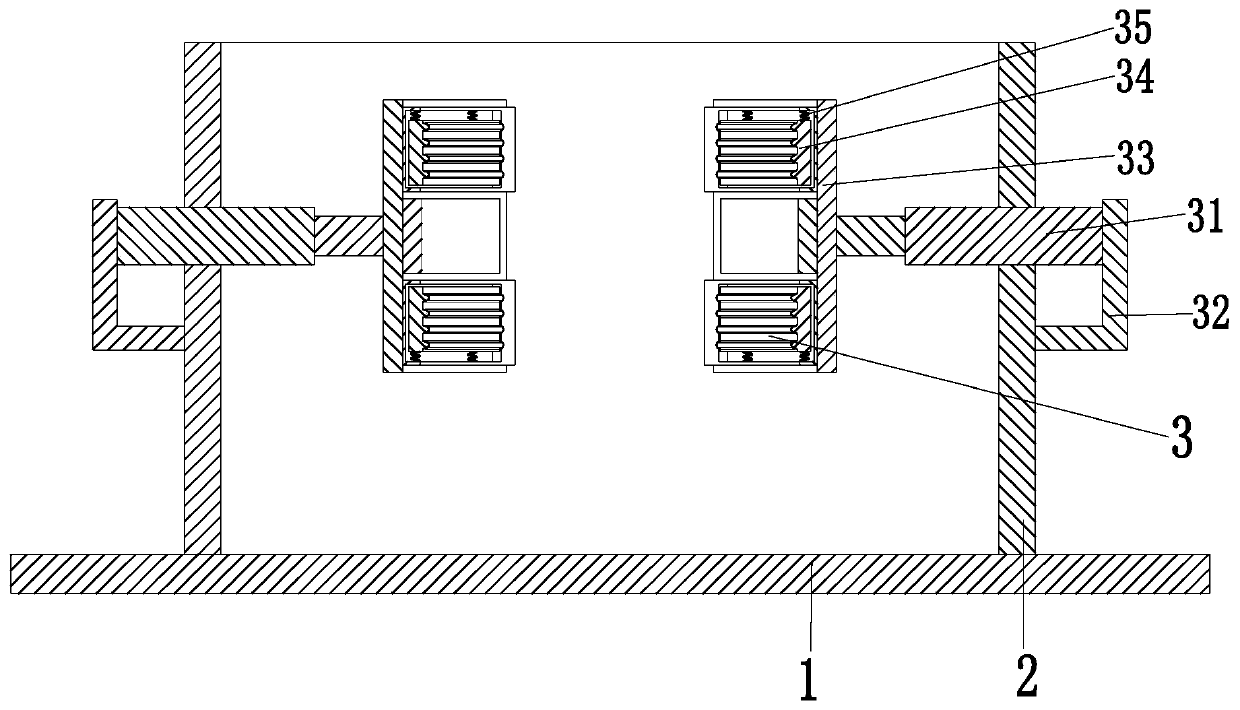
[0032] Such as Figure 1 to Figure 8 As shown, a vacuum switch tube ceramic shell positioning assembly mold includes a support plate 1, a placement sleeve 2, a clamping device 3, a hanging plate 4, a positioning cylinder 5 and a positive positioning device 6, and the top of the support plate 1 is installed There is a placement sleeve 2, a clamping device 3 is installed on the left and right ends of the placement sleeve 2, and the positioning device 6 is located above the placement sleeve 2. Hanging plate 4 is installed on the upper end of the hanging plate 4, and mounting holes are ...


PUM


Abstract

The invention relates to a positioning and assembling die for a ceramic shell of a vacuum switch tube. The positioning and assembling die comprises a supporting plate, a placement sleeve, clamping devices, a lifting plate, a positioning air cylinder and an alignment device, wherein the placement sleeve is arranged on the top of the supporting plate, and the left end and the right end of the placement sleeve are provided with the clamping devices respectively; the alignment device is positioned above the placement sleeve; the top of the alignment device is connected with the lower end of the positioning air cylinder; the lifting plate is installed on the upper end of the positioning air cylinder, and mounting holes are uniformly formed in the lifting plate; and the alignment device comprises an alignment clamping sleeve, a locking clamping jaw, a buffer spring, an adjusting column, a clamping-pressing column, a clamping-pressing spring, a laminating plate, a pushing column and a pushingspring. According to the positioning and assembling die, the problems can be solved as follows: the welding effect of the switch tube is poor due to the fact that a certain error exists in manual operation in the prior art, a three-jaw chuck easily causes damage to the ceramic shell and the three-jaw chuck cannot be attached to the appearance of the ceramic shell when the ceramic shell is lockedby the three-jaw chuck.

Description

technical field [0001] The invention relates to the technical field of electric power accessories processing, in particular to a positioning and assembling mold for a ceramic shell of a vacuum switch tube. Background technique [0002] The ceramic vacuum switch tube is the core component of the medium and high voltage power switch. Its main function is to quickly extinguish the arc and suppress the current after the medium and high voltage circuit is cut off through the excellent insulation of the vacuum inside the tube, so as to avoid accidents and accidents. Such as Figure 8 As shown, the ceramic vacuum switch tube is composed of an airtight insulating shell made of ceramics, a cover plate, and a conductive rod. The outer end of the ceramic shell is encapsulated by the cover plate; the connection between the ceramic shell and the cover plate is generally carried out by brazing. After the position of the cover plate and the ceramic shell is manually positioned, the ceramic...

Claims


Application Information

Patent Timeline
Patent Type & Authority Applications(China)
IPC IPC(8): H01H11/00B23K3/08
CPCB23K3/087H01H11/00
Inventor 郭海涛程业春方坤棉
Owner JINHUA MINGZHENG TECH CO LTD
Why Eureka
Try Eureka