
Etching groove, method for conveying etching liquid and etching system

An etching system and etching tank technology, applied in the field of etching systems, can solve the problems of inter-chip etching uniformity, reduce intra-chip etching uniformity, and uneven flow rate, etc., and achieve improved intra-chip etching uniformity Efficiency and inter-chip etching uniformity, prevention of inter-chip cross-contamination, uniform and stable flow rate

Inactive Publication Date: 2019-07-26
HUAIAN IMAGING DEVICE MFGR CORP
View PDF3 Cites 4 Cited by
  • Summary
  • Abstract
  • Description
  • Claims
  • Application Information

AI Technical Summary

Problems solved by technology

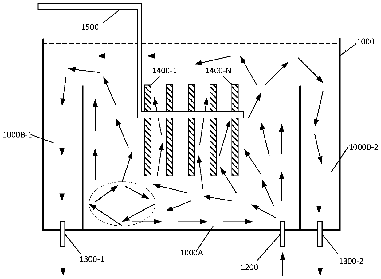
[0004] Since the conventional etching tank is only provided with a liquid inlet valve, the flow of etching liquid in the etching tank is uneven
For example, when the etchant flows through the surface of the object to be etched, the flow rate is not uniform, which will reduce the uniformity of etching within the chip
Moreover, the fluctuation of the etching liquid flow in the upper and lower parts of the etching tank is also uneven. This uneven fluctuation is likely to cause eddy currents and cause shaking of the object to be etched, so that the etching uniformity between sheets is affected. influences
In addition, the direction of the etching liquid flow is not uniform and unstable, which will cause the contamination to diffuse in the etching groove, so as to cause cross-contamination between wafers

Method used


Image

  • Etching groove, method for conveying etching liquid and etching system
  • Etching groove, method for conveying etching liquid and etching system
  • Etching groove, method for conveying etching liquid and etching system

Examples


example 1

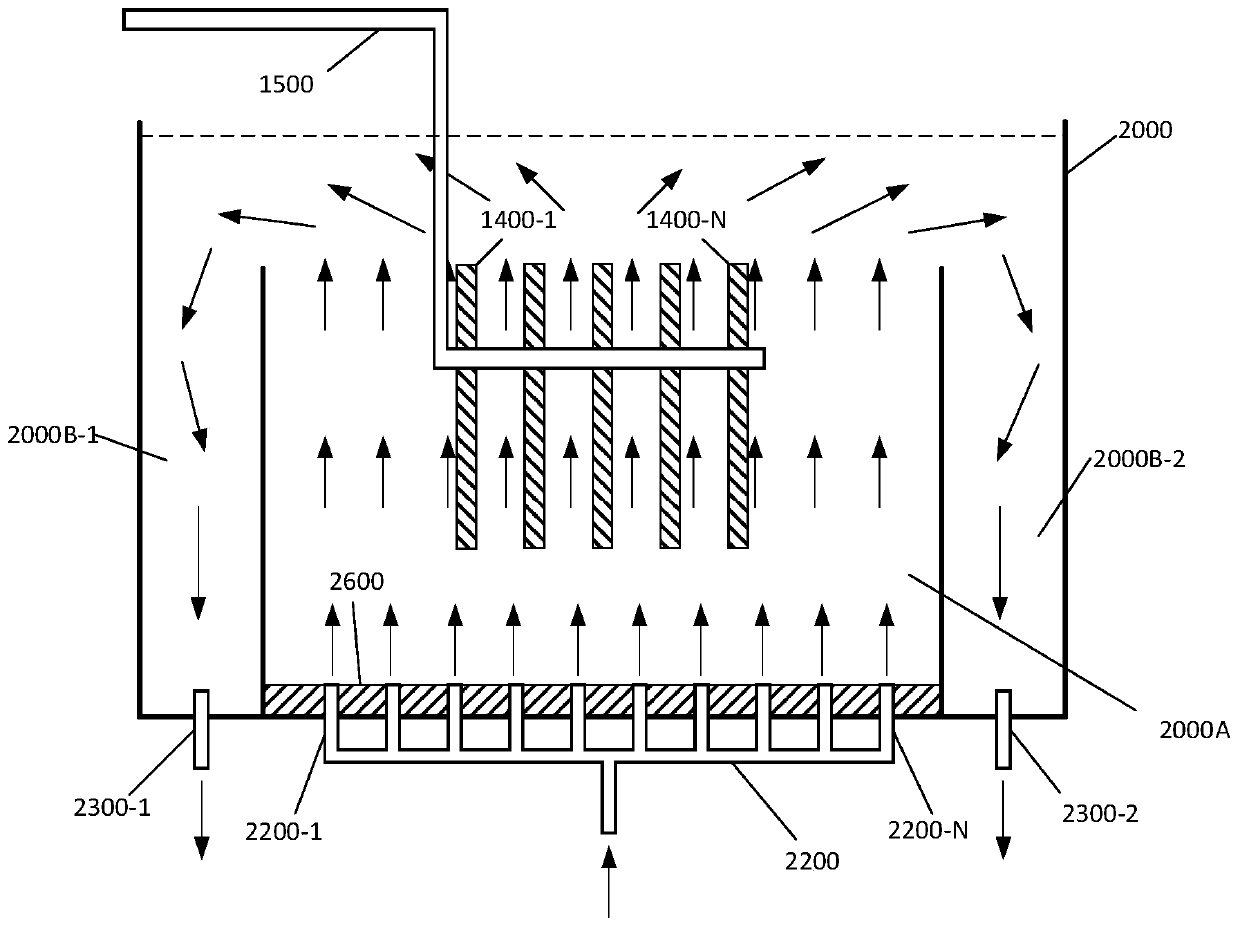
[0070] Example 1, an etching groove, wherein, the etching groove comprises:

[0071] A plurality of delivery nozzles, the plurality of delivery nozzles are evenly distributed on the bottom of the etching tank, and the plurality of delivery nozzles are configured to deliver the etching liquid into the etching tank in parallel.

example 2

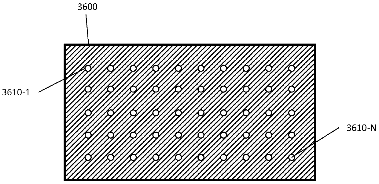
[0072] Example 2. The etching groove as described in Example 1, wherein:

[0073] The etching tank also includes a first screen, the first screen is positioned at the bottom of the etching tank and has a plurality of holes, each delivery nozzle in the plurality of delivery nozzles is fixed on the corresponding slots in the plurality of slots of the first screen.

example 3

[0074] Example 3. The etching groove as described in Example 2, wherein:

[0075] The opening of each delivery nozzle in the plurality of delivery nozzles is not higher than the upper surface of the first screen.


PUM


Abstract

The invention relates to an etching groove. The etching groove comprises a plurality of conveying nozzles, wherein the plurality of conveying nozzles are uniformly distributed at the bottom of the etching groove, and the plurality of conveying nozzles are configured to convey the etching liquid to the etching groove in parallel.

Description

technical field [0001] The present disclosure relates to the field of semiconductors, in particular, to an etching tank, a method for transporting etching solution, and an etching system. Background technique [0002] In semiconductor wet etching processes, trench wet etching has always occupied a large proportion. The development of the groove wet etching process has become more mature and stable. As the size of the object to be etched (for example, a silicon wafer) increases and the size of the feature process shrinks, the uniformity of the film on the wafer has an increasing impact on the yield of the product, and the uniformity of wet etching is also increasing. Gradually become a key parameter affecting yield. [0003] In wet bath etching, the objects to be etched are usually immersed in batches in the etching solution in the etching bath. A conventional etching tank is divided into an inner tank body and an outer tank body, wherein a liquid inlet valve is provided a...

Claims


Application Information

Patent Timeline
Patent Type & Authority Applications(China)
IPC IPC(8): H01L21/67
CPCH01L21/67086
Inventor 卢思源张文福刘家桦叶日铨
Owner HUAIAN IMAGING DEVICE MFGR CORP
Learn More