Runner structure of a rubber mold

A rubber mold and runner technology, applied in the field of runner structure of rubber molds, can solve the problems of low temperature at the inner core, high scrap rate, lower production efficiency, etc., and achieve the effect of ensuring temperature

Active Publication Date: 2020-01-07
NINGBO TUOPU GROUP CO LTD
View PDF1 Cites 0 Cited by
  • Summary
  • Abstract
  • Description
  • Claims
  • Application Information

AI Technical Summary

Problems solved by technology

Since the mold has multiple cavities, the geometric path of the rubber runner will be different in length, and the surface roughness of the rubber runner will be different, so the flow of rubber material in the rubber runner will be unbalanced, and the speed to reach the cavity will be different. Inconsistency, which will lead to lack of rubber in the rubber product formed by injection molding in the final cavity, which will become a waste product with a high scrap rate; in addition, due to the characteristics of rubber flow, that is, wall adhesion, the temperature at the rubber wall in the flow channel is high, The temperature at the inner core is low, which will also lead to defects in the finished rubber product, causing the product in some cavities to lack rubber, which will also lead to a longer single-cycle vulcanization time and reduce production efficiency.

Method used


Image

  • Runner structure of a rubber mold
  • Runner structure of a rubber mold
  • Runner structure of a rubber mold

Examples


Embodiment

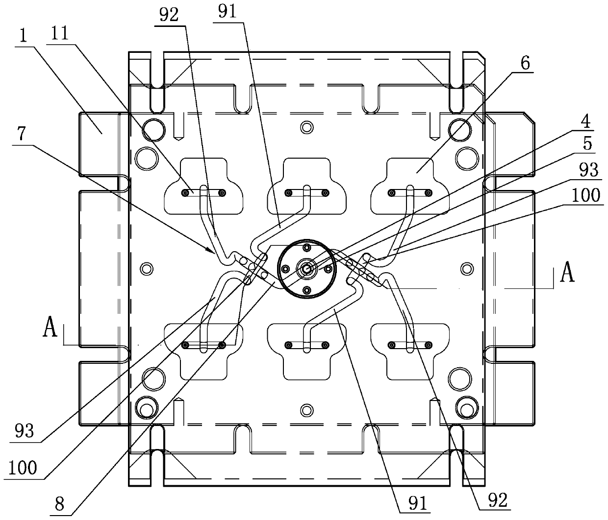
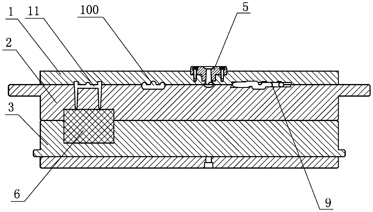
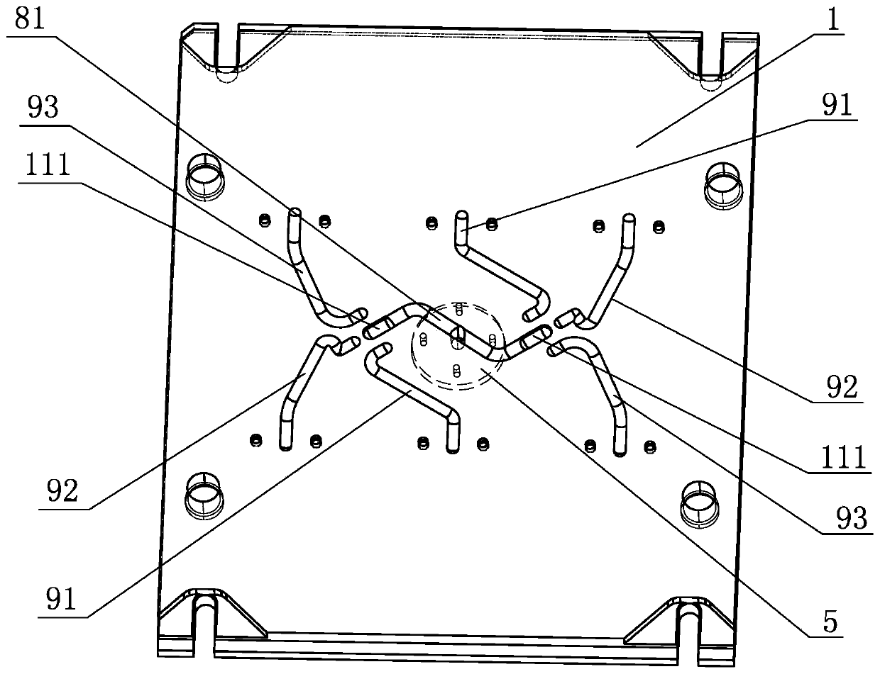
[0026] Embodiment: As shown in the figure, a runner structure of a rubber mold includes a runner plate 1, an upper mold plate 2 and a lower mold plate 3 arranged from top to bottom, and the runner plate 1 is provided with a glue injection hole 4. A glue injection nozzle 5 is inserted in the glue hole 4, at least two cavities 6 are processed between the upper template 2 and the lower template 3, and a runner 7 is provided between the runner plate 1 and the upper template 2, and the runner 7 includes A primary flow channel 8 with a circular cross section, at least two secondary flow channels 9, two chambers 100 for inverting the rubber material, and a tertiary flow channel 11 corresponding to the secondary flow channel 9, the primary The middle part of the flow channel 8 communicates with the glue injection hole 4, and the two ends of the primary flow channel 8 are respectively connected with chambers 100. The primary flow channel 8 includes the upper half flow channel 81 arrange...


PUM


Abstract

The invention discloses a runner structure of a rubber mold. A runner comprises a first-stage runner with a circular cross section, at least two second-stage runners, two chambers used for overturningrubber materials and a third-stage runner. The middle portion of the first-stage runner communicates with a rubber injection hole. The two ends of the first-stage runner are connected with the chambers correspondingly. The first-stage runner comprises an upper half runner arranged on a runner plate and a lower half runner arranged on an upper mold plate. Each chamber comprises an inlet connectionpipe and at least one outlet connection pipe, wherein the inlet connection pipe is composed of an upper half inlet connection pipe arranged on the runner plate and a lower half inlet connection pipearranged on the upper mold plate, the cross section of the upper half inlet connection pipe is in an inverted-U shape, the cross section of each outlet connection pipe is in a U shape, and the outletconnection pipes are arranged on the upper mold plate. The runner structure has the beneficial effects that the rubber materials pass through the chambers which are used for overturning the rubber materials, the rubber materials at the position of an inner core and the rubber materials at the positions attaching to the wall of the runner are mixed to enable the temperature to be uniform, flowing is more balanced, forming of a product is facilitated better, and the vulcanizing efficiency of the product in a cavity and the yield are increased.

Description

technical field [0001] The invention relates to a rubber mold, in particular to a runner structure of the rubber mold. Background technique [0002] A large number of rubber molds are used in the production process of existing auto parts, and a large part of conventional rubber molds are multi-cavity molds. The existing multi-cavity rubber mold includes a runner plate, an upper template and a lower template from top to bottom. The runner plate is provided with a glue injection nozzle, the upper template is provided with a rubber runner, and the upper template and the lower template are processed. There are multiple cavities, and the rubber runner is connected with the cavity, and the rubber flows in the rubber runner, and finally flows into the cavity for injection molding. Since the mold has multiple cavities, the geometric path of the rubber runner will be different in length, and the surface roughness of the rubber runner will be different, so the flow of rubber material...

Claims


Application Information

Patent Timeline
Patent Type & Authority Patents(China)
IPC IPC(8): B29C45/27B29C45/32
CPCB29C45/2725B29C45/32
Inventor 韦雪雯
Owner NINGBO TUOPU GROUP CO LTD
Why Eureka
Try Eureka