Method for rapidly evaluating maximum wind power permeability under consideration of frequency accumulation effect
A cumulative effect and penetration rate technology, applied in the field of rapid assessment of maximum wind power penetration rate, it can solve the problems of lower inertia level, worsening system frequency response, unfavorable system security, etc., and achieve the effect of ensuring safe and stable operation.
- Summary
- Abstract
- Description
- Claims
- Application Information
AI Technical Summary
Problems solved by technology
Method used
Image
Examples
Embodiment 1
[0049] Those skilled in the art can understand that, unless otherwise defined, all terms (including technical terms and scientific terms) used herein have the same meaning as commonly understood by those of ordinary skill in the art to which this invention belongs. It should also be understood that terms such as those defined in commonly used dictionaries should be understood to have a meaning consistent with the meaning in the context of the prior art, and unless defined as herein, are not to be interpreted in an idealized or overly formal sense Explanation.
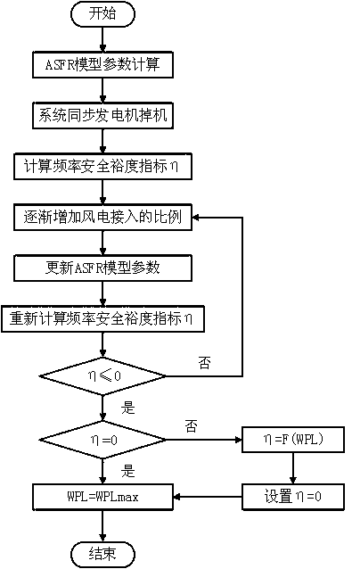
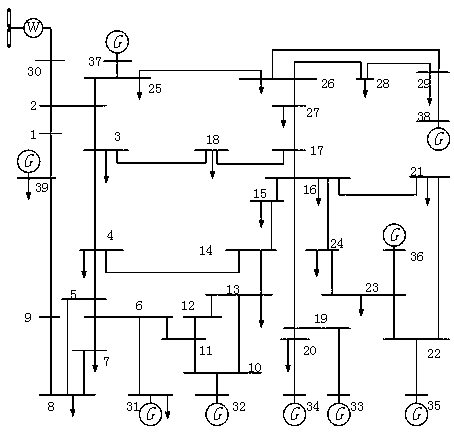
[0050] In this embodiment, the IEEE39 node test system is used as a simulation example to evaluate the maximum wind power penetration level of the regional power grid. The system loads are all static loads, and wind power is connected to node 30 to directly replace traditional synchronous generators of the same capacity. figure 2 This is the revised topological diagram of the IEEE39 node system including wind power in ...
Embodiment 2
[0109] When defining the frequency safety margin index η based on cumulative effects, the expression of the frequency safety margin index η can be expressed as:
[0110]
[0111] The lowest value of defined system frequency is actually less than f cr The time is tb, according to the severity of the system frequency offset, t b There are three types of situations for the value of , and the frequency trajectory curves of the three situations are as follows Figure 4a , Figure 4b , Figure 4c shown.
[0112] The calculation results of the system frequency safety margin index are different for each type of situation:
[0113] (a)t b =0, the frequency safety margin index η is:
[0114]
[0115] (b)0b cr When , the frequency safety margin index η is:
[0116]
[0117] (c)t b >t cr When , the frequency safety margin index η is:
[0118]
[0119] In this embodiment, the frequency safety and stability margin index η may be used to perform a safety warning on the...
PUM
 Abstract
Description
Claims
Application Information
 - R&D
- Intellectual Property
- Life Sciences
- Materials
- Tech Scout
- Unparalleled Data Quality
- Higher Quality Content
- 60% Fewer Hallucinations
Browse by: Latest US Patents, China's latest patents, Technical Efficacy Thesaurus, Application Domain, Technology Topic, Popular Technical Reports.
© 2025 PatSnap. All rights reserved.Legal|Privacy policy|Modern Slavery Act Transparency Statement|Sitemap|About US| Contact US: help@patsnap.com


