A Screw Assembly Tool Based on Pneumatic Slip Ring Structure

A technology for assembling tools and screws, which is applied in the direction of manufacturing tools, metal processing, metal processing equipment, etc., can solve the problems of increasing weight, occupying a large space, and trachea entanglement, and achieve the effect of avoiding air leakage and trachea entanglement

Active Publication Date: 2020-10-16
HARBIN INST OF TECH
View PDF8 Cites 0 Cited by
  • Summary
  • Abstract
  • Description
  • Claims
  • Application Information

AI Technical Summary

Problems solved by technology

However, if the gripper is driven by a motor to perform the clamping movement, the motor and transmission mechanism will take up a lot of space and will also greatly increase the weight
And because in the actual screwing assembly work process, the screw needs to be screwed dozens of times before it can be tightened, directly connecting the air pipe to the cylinder will cause the air pipe to be entangled

Method used


Image

  • A Screw Assembly Tool Based on Pneumatic Slip Ring Structure

Examples


specific Embodiment approach 1

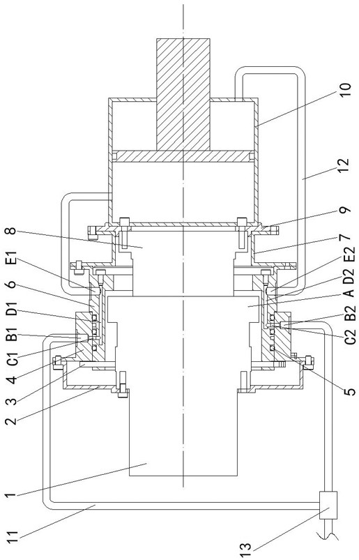
[0009] Specific implementation manner one: such as figure 1 As shown, the present invention discloses a screw assembly tool based on a pneumatic slip ring structure, including flange one 2, limit ring 3, fixed ring 4, rotating ring 6, flange two 7, flange three 9. , Cylinder 10, switch valve 13, electric rotating mechanism, two intake pipes 11 and two outlet pipes 12,

[0010] The electric rotating mechanism includes a fixed shaft 1 and a rotating shaft 8. One end of the fixed shaft 1 is detachably and fixedly connected to the end of the mechanical arm, and the other end of the fixed shaft 1 is sleeved on the outside of one end of the rotating shaft 8. The outer side wall is provided with an annular mounting boss A along the circumferential direction. The outer side of the electric rotating mechanism is sequentially covered with flange 1, stop ring 3, fixed ring 4, rotating ring 6, and flange 2, 7 from the fixed shaft to the rotating shaft. One end of the rotating ring 6 is slee...

specific Embodiment approach 2

[0011] Specific implementation manner two: such as figure 1 As shown, this embodiment is a further description of the first embodiment. Three sealing rings 5 ​​are provided between the fixed ring 4 and the rotating ring 6, and the three sealing rings 5 ​​are alternately arranged with two annular grooves. ; The sealing rings 5 ​​on both sides are to ensure the sealing between the adjacent annular grooves and the outside world, and the sealing ring 5 in the middle is to ensure that there will be no communication between the two annular grooves. The assembly process In each channel, a certain amount of grease is added to reduce the rotational resistance between the fixed ring 4 and the rotating ring 6.

[0012] The cylinder 10 is an SMC type finger cylinder, the model is: MHS3-40D, which is an existing technology and can be purchased from outside.

[0013] When using the clamping screw of the present invention, turn the switch valve 13 to one side, and pass high-pressure gas into one...


PUM


Abstract

The invention discloses a bolt assembly tool based on a pneumatic slide ring structure, and belongs to the technical field of bolt assembly. A fixed shaft with a ring-shaped mounting lug boss sleevesoutside a rotary shaft, one end of a rotary ring sleeves outside the ring-shaped mounting lug boss, and the other end of the rotary ring sleeves outside the rotary shaft; a fixed ring sleeves outsidethe rotary ring, and is connected to a flange plate I; the flange plate I is connected to the ring-shaped mounting lug boss; the rotary ring and the fixed ring are fitted to a limiting ring; the limiting ring is fixedly arranged outside the ring-shaped mounting lug boss; a flange plate II is connected to the rotary ring and a flange plate III; a gas cylinder I is connected to the rotary shaft through the flange plate III; the fixed ring is provided with a gas inlet through hole; the rotary ring is provided with a ring-shaped groove, a gas path and a gas outlet through hole; a gas inlet tube, the corresponding gas inlet through hole, the ring-shaped groove, the gas path and the gas outlet through hole are in communication; the gas outlet through hole communicates with the corresponding gasoutlet tube; and the gas outlet tube communicates with the gas cylinder. The bolt assembly tool can simultaneously accomplish two-freedom motion of clamping and bolt screwing-up, and can operate innerhexagonal cylinder bolts of different models.

Description

Technical field [0001] The invention relates to a screw assembly tool based on a pneumatic slip ring structure, belonging to the technical field of screw assembly. Background technique [0002] The robot end tool is a device that enables the robot to directly contact the workpiece and perform tasks. Robot end tools can be customized with different functions according to different usage requirements, such as cutting tools, multi-function operating tools, safety nut removal tools, fuel filling tools, socket wrench tools, etc. In industrial applications, the end gripper of the robot end tool is usually two-finger or three-finger. However, these grippers are rarely able to perform a rotational movement while performing a clamping action. Screw assembly is a very common production line operation task, and the use of robots to complete this operation task can greatly improve production efficiency. This work requires not only tools that can hold the bolts, but also tools that can com...

Claims


Application Information

Patent Timeline
Patent Type & Authority Patents(China)
IPC IPC(8): B23P19/06
CPCB23P19/006B23P19/06
Inventor 谢宗武张琦刘阳赵晓宇孙奎刘宏
Owner HARBIN INST OF TECH
Why Eureka
Try Eureka