Rain grate lifter

A rain grate and wheel technology, which is applied to lifting devices, crowbars, etc., can solve problems such as difficulty in lifting, and achieve the effect of convenient replacement.

Inactive Publication Date: 2019-07-30
杨小荟
View PDF8 Cites 4 Cited by
  • Summary
  • Abstract
  • Description
  • Claims
  • Application Information

AI Technical Summary

Problems solved by technology

[0003] In order to overcome the shortcoming that due to the long time, the silt is covered on the rain grate, it is difficult for people to lift it, and people need to manually put it back to the original position when lifting the rain grate, which is relatively laborious. The technical problems to be solved are: Provide a rain grate lifter that can make it easier for people to lift the rain grate, and is convenient for people to put the rain grate back to its original position, and is relatively labor-saving

Method used


Image

  • Rain grate lifter
  • Rain grate lifter
  • Rain grate lifter

Examples


Embodiment 1

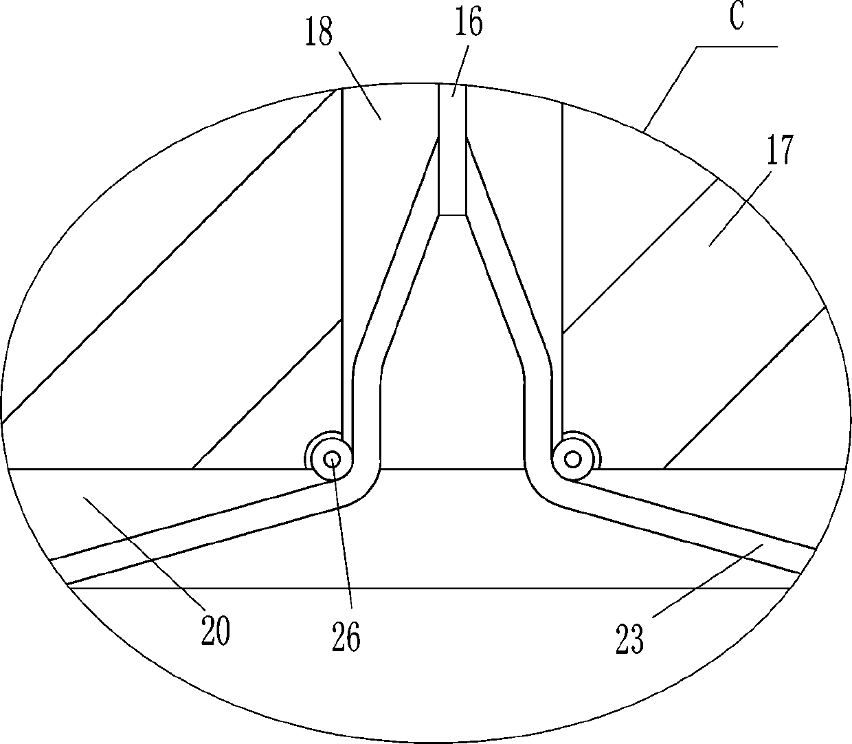
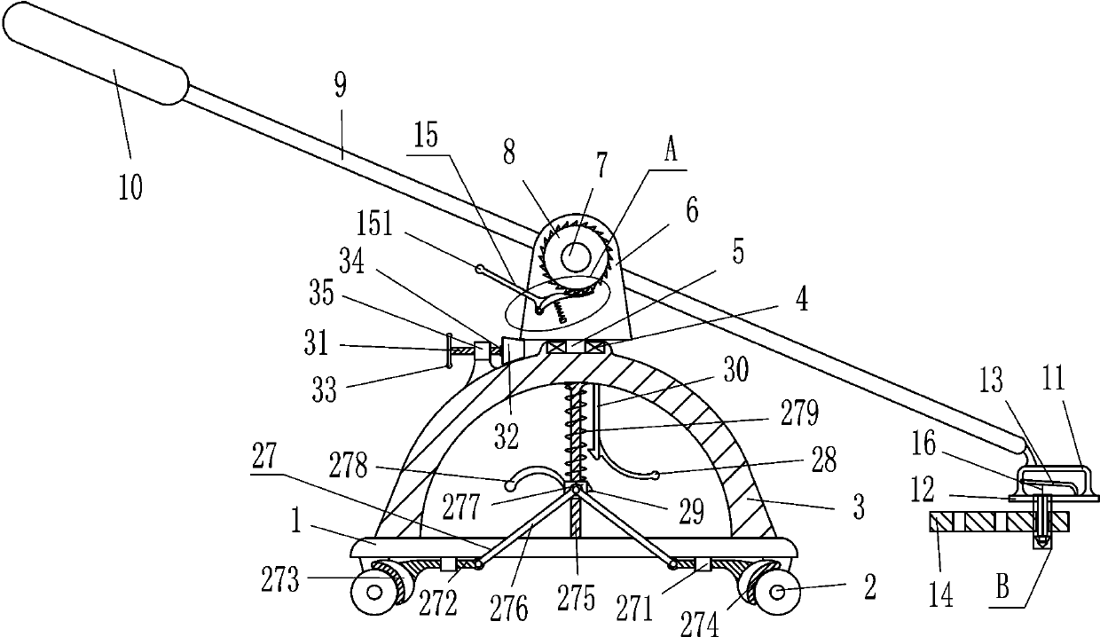
[0017] A rain grate lifter, such as Figure 1-4 As shown, it includes base plate 1, wheel 2, arc frame 3, bearing seat 4, rotating shaft 5, support plate 6, rotating rod 7, ratchet 8, swing rod 9, grip rod 10, n-shaped rod 11, and horizontal plate 12 , the first movable rod 13, the clamping device 15, the pull wire 16, the vertical bar 17, the second spring 21, the block 22, the branch line 23, the sealing ring 24, the horizontal slider 25 and the guide wheel 26, and the left and right sides of the bottom plate 1 The side symmetric type is equipped with wheels 2, the base plate 1 is connected with the wheels 2 through bolt connection, the arc frame 3 is installed in the middle of the top of the base plate 1, the arc frame 3 is connected with the base plate 1 through bolt connection, and the arc frame 3 A bearing seat 4 is embedded in the middle of the outer surface, and the rotating shaft 5 is connected to the bearing in the bearing seat 4. The rotating shaft 5 is connected to...

Embodiment 2

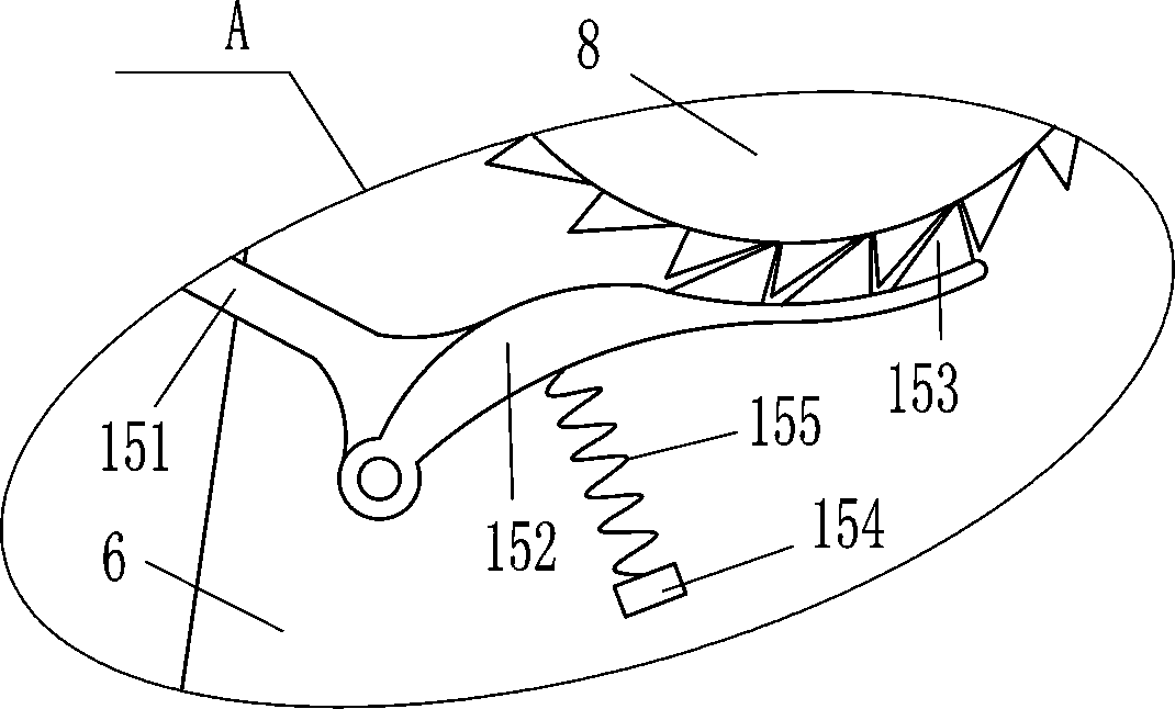
[0019] A rain grate lifter, such as Figure 1-4 As shown, it includes base plate 1, wheel 2, arc frame 3, bearing seat 4, rotating shaft 5, support plate 6, rotating rod 7, ratchet 8, swing rod 9, grip rod 10, n-shaped rod 11, and horizontal plate 12 , the first movable rod 13, the clamping device 15, the pull wire 16, the vertical bar 17, the second spring 21, the block 22, the branch line 23, the sealing ring 24, the horizontal slider 25 and the guide wheel 26, and the left and right sides of the bottom plate 1 The side symmetrical type is equipped with wheels 2, the arc frame 3 is installed in the middle of the top of the bottom plate 1, the middle part of the outer surface of the arc frame 3 is embedded with a bearing seat 4, the rotating shaft 5 is connected with the bearing in the bearing seat 4, and the top of the rotating shaft 5 The support plate 6 is fixedly connected, and the rotating rod 7 is rotatably installed in the middle of the upper part of the supporting pla...

Embodiment 3

[0022] A rain grate lifter, such as Figure 1-4 As shown, it includes base plate 1, wheel 2, arc frame 3, bearing seat 4, rotating shaft 5, support plate 6, rotating rod 7, ratchet 8, swing rod 9, grip rod 10, n-shaped rod 11, and horizontal plate 12 , the first movable rod 13, the clamping device 15, the pull wire 16, the vertical bar 17, the second spring 21, the block 22, the branch line 23, the sealing ring 24, the horizontal slider 25 and the guide wheel 26, and the left and right sides of the bottom plate 1 The side symmetrical type is equipped with wheels 2, the arc frame 3 is installed in the middle of the top of the bottom plate 1, the middle part of the outer surface of the arc frame 3 is embedded with a bearing seat 4, the rotating shaft 5 is connected with the bearing in the bearing seat 4, and the top of the rotating shaft 5 The support plate 6 is fixedly connected, and the rotating rod 7 is rotatably installed in the middle of the upper part of the supporting pla...


PUM


Abstract

The invention relates to a lifter, in particular to a rain grate lifter. With the rain grate lifter, people can lift a rain grate more easily, and place the rain grate back in place conveniently, andthe rain grate lifter saves labor. According to the technical scheme, the rain grate lifter comprises a bottom plate, wheels, an arc-shaped frame, a bearing seat, a rotating shaft, a supporting plate,a rotating rod, a ratchet wheel, a swing rod, a holding rod, an n-shaped rod, a transverse plate, a first movable rod, a clamping device and the like; the wheels are symmetrically arranged on the left side and the right side of the bottom of the bottom plate; the arc-shaped frame is arranged in the middle of the top of the bottom plate; and the bearing seat is embedded in the middle of the outerside surface of the arc-shaped frame. According to the rain grate lifter, clamping blocks penetrates through holes of the rain grate to clamp the rain grate, the left part of a swing rod is pulled toswing downwards, then the clamping blocks are capable of moving upwards to lift the rain grate, and the rain grate does not need to be lifted directly with hands, so that the operation is easier and requires less effort, and the rain grate is more convenient to place back.

Description

technical field [0001] The invention relates to a lifter, in particular to a rain grate lifter. Background technique [0002] In urban construction, rain grates are installed at the entrance of the sewer to prevent people from falling into the sewer, but the long-term use of the sewer needs to be cleaned, and the rain grate needs to be lifted. Long, the mud and sand are covered on the rain grate, making it difficult for people to lift it, and people need to manually put it back to the original position after lifting the rain grate, which is laborious, so many people need to lift the rain grate at the same time, and use a hammer first Beat around the rain grate, so the labor cost is high and the operation is troublesome. Contents of the invention [0003] In order to overcome the shortcoming that due to the long time, the silt is covered on the rain grate, it is difficult for people to lift it, and people need to manually put it back to the original position when lifting t...

Claims


Application Information

Patent Timeline
Patent Type & Authority Applications(China)
IPC IPC(8): B66F15/00
CPCB66F15/00
Inventor 杨小荟
Owner 杨小荟
Why Eureka
Try Eureka