

Surveying device for measuring horizontal displacement of soil body
A technology of horizontal displacement and inclination measuring device, which is applied in the field of foundation soil survey, construction, infrastructure engineering and other directions, can solve the problems of increased monitoring cost, high cost, high price of inclination sensor, etc., and achieve low price and reduce monitoring cost. Effect
- Summary
- Abstract
- Description
- Claims
- Application Information
AI Technical Summary
Problems solved by technology
Method used
Image

Examples
Embodiment Construction
[0015] The present application is further described in conjunction with the following examples.
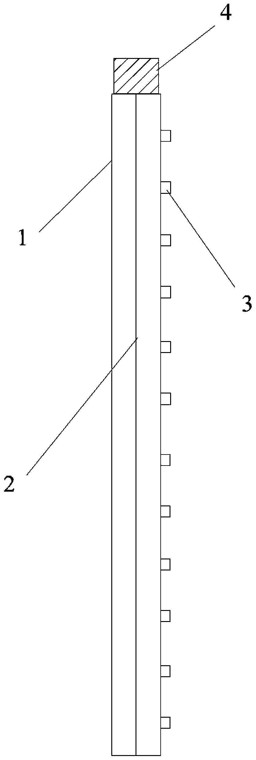
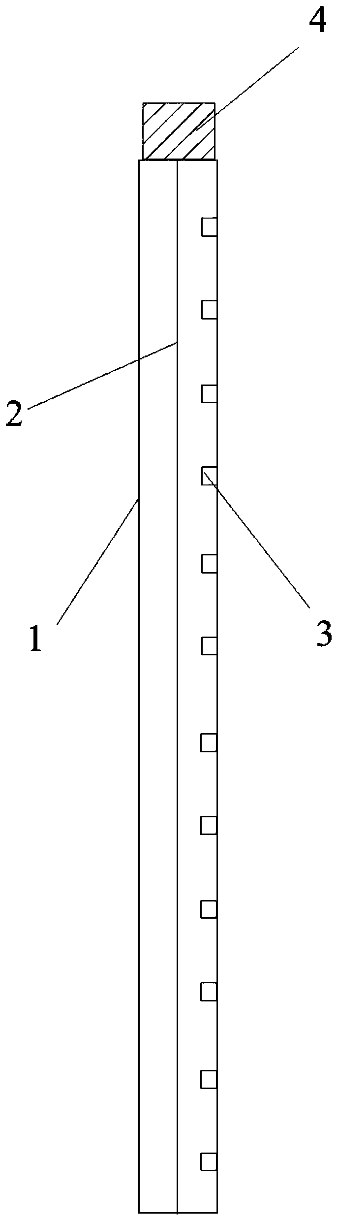
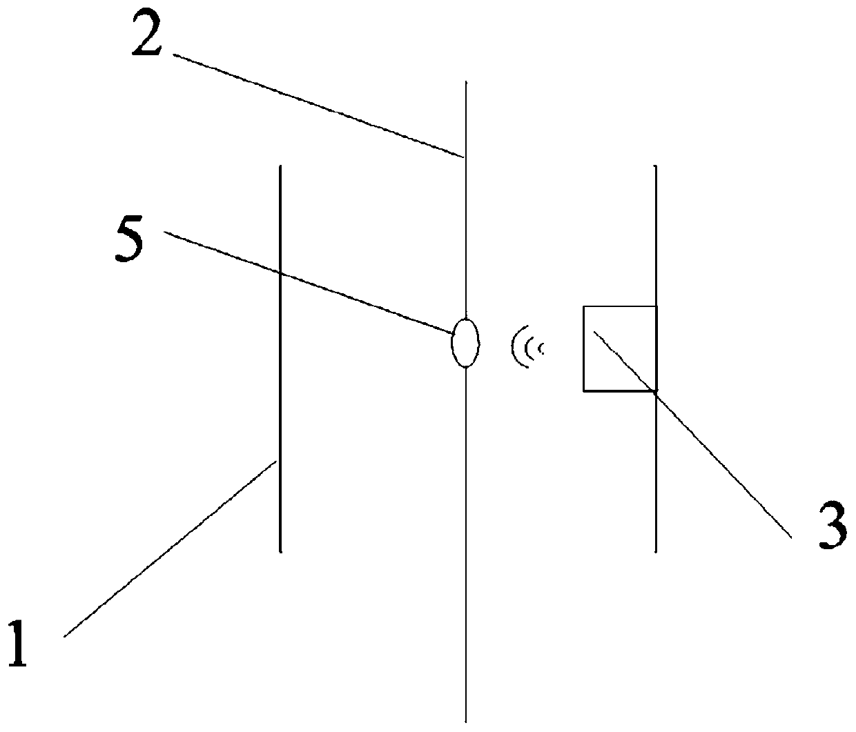
[0016] An inclinometer device for measuring the horizontal displacement of soil according to the present application is used for observing the horizontal displacement inside the soil. Such as figure 1 and figure 2 As shown, it includes an inclinometer tube 1 , a tension member 2 , a plurality of distance measuring sensors 3 and a data acquisition and processing device 4 connected to each distance measuring sensor 3 . The inclinometer tube 1 can be a PVC inclinometer tube or an inclinometer tube made of other materials, as long as it can be used in conjunction with the distance measuring sensor 3 . The tension member 2 can be metal or non-metal material with low thermal expansion coefficient, such as indium steel wire. Preferably, when the distance measuring sensor 3 is an eddy current or magnetic induction sensor, the tension member 2 is made of a metal material. The distance...
PUM
 Abstract
Description
Claims
Application Information