Water flow regulator

A regulator and water flow technology, applied in the field of sanitary ware, can solve the problems of long time in the atomization process, long atomization distance of droplets, and influence on the atomization effect, so as to achieve uniform distribution of the number of droplets, good atomization effect, and structure compact effect

Pending Publication Date: 2019-08-02
宁波杰敏卫浴科技有限公司
View PDF1 Cites 0 Cited by
  • Summary
  • Abstract
  • Description
  • Claims
  • Application Information

AI Technical Summary

Problems solved by technology

[0003] But the defect that this atomizing nozzle exists is: 1, because a plurality of supply passages of this patent are on the same horizontal plane, so the fluid swirls and collides on the horizontal plane, if want to reach better atomization effect, then The volume of the nozzle will be larger; and the atomization nozzle will cause the droplet atomization distance to be long, the pressure loss will be large, and the atomization process will take a long time, which will affect the atomization effect; 2. In order to prevent the water that rotates along the wall of the vortex chamber The jet flow is transferred to the center of the vortex chamber, the patent needs to set a protrusion, but for the sanitary industry that does not have high requirements on water quality, which contains impurities such as tiny particles, the more parts that the nozzle contains that are in contact with water, the more it is used The greater the probability of impurities in the water attaching, it is easy to cause blockage of the waterway, and the user experience is poor

Method used


Image

  • Water flow regulator
  • Water flow regulator
  • Water flow regulator

Examples


Embodiment Construction

[0020] The present invention will be further described in detail below in conjunction with the accompanying drawings and embodiments.

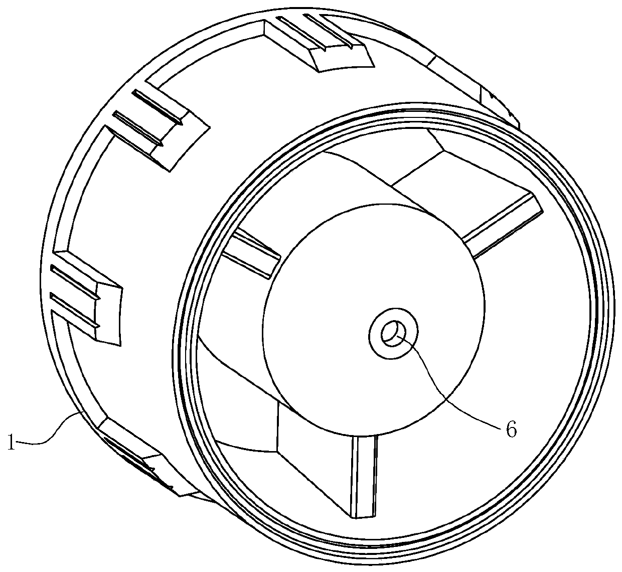
[0021] After the liquid fluid (such as water) is sprayed from the nozzle hole 6, it will undergo two processes of primary atomization and secondary atomization. If the injection pressure is not high enough, a continuous circular jet will be formed at the nozzle hole 6—a liquid with a large diameter. Droplets, this process is called the primary atomization process, and the secondary atomization process is the further breaking of large-diameter droplets to form a large number of fine droplets.

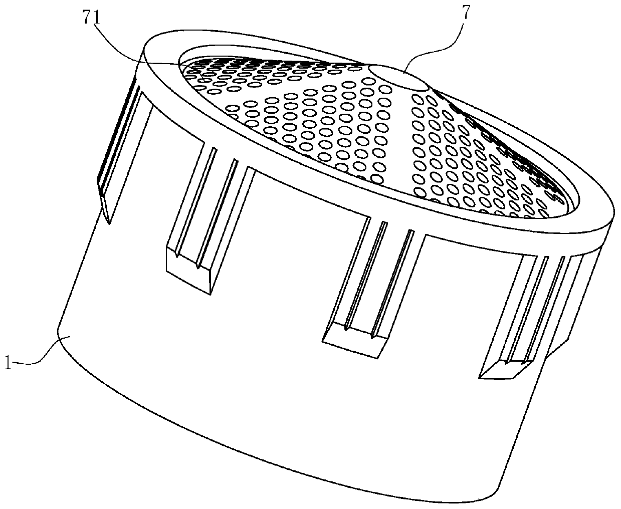
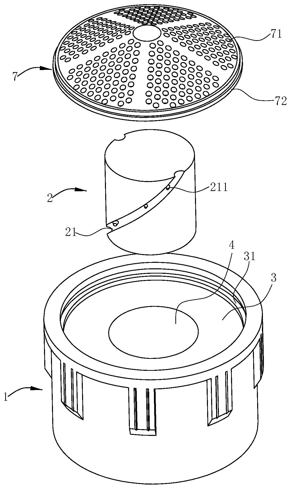
[0022] Such as Figure 1~5 As shown, the water flow regulator of this preferred embodiment includes a casing 1, an inner core 2 and a cover 7. Along the flow direction of the fluid, the casing 1 is sequentially provided with a connected liquid inlet chamber 3, an accommodating chamber 4, and a swirl chamber. 5 and the nozzle hole 6, the liquid inlet cha...


PUM


Abstract

The invention relates to a water flow regulator. The water flow regulator comprises a housing, wherein in a flowing direction of fluid, a liquid inlet cavity for taking in liquid, a whirling cavity for whirling and accelerating fluid and a spray hole for spraying out the fluid, which are in communication, are sequentially formed in the housing; the diameter of the whirling cavity is gradually reduced in the flowing direction of the fluid; an accommodating cavity positioned between the liquid inlet cavity and the whirling cavity is further arranged on the housing; an inner core which is fixedlyarranged relative to the accommodating cavity is inserted into the accommodating cavity; at least two channels for allowing fluid to pass through in the peripheral direction are formed between the outer wall of the inner core and the inner wall of the accommodating cavity; the two ends of each channel separately communicate with the liquid inlet cavity and the whirling cavity; and each channel spirally extends along the axis of the inner core. The regulator starts to generate rotation and collision after water flow enters the channels; compared with a way of colliding and rotating water flowon the horizontal plane, the water flow regulator disclosed by the invention can achieves a smaller size, and is more compact in structure on the premise of achieving the same atomizing effect.

Description

technical field [0001] The invention belongs to the field of sanitary ware, and in particular relates to a water flow regulator used for water outlet devices such as faucets and showers. Background technique [0002] In the bathroom industry, such as showers or faucets, if there is no impact force under low pressure, the user experience will not be good, so a water flow regulator is usually installed in the shower or faucet. The "atomizing nozzle for sanitary water outlet and sanitary faucet with water outlet" disclosed by the Chinese invention patent application of ZL20110316146.2 (publication number CN104043544A) known as a spraying nozzle under pressure. An atomizing nozzle for liquids, which can be used as a spout for a sanitary water tap or as a shower head. The atomizing nozzle has a swirl chamber into which at least one supply channel oriented transversely to the nozzle longitudinal axis and entering approximately tangentially into the swirl chamber opens, wherein th...

Claims


Application Information

Patent Timeline
Patent Type & Authority Applications(China)
IPC IPC(8): B05B1/34B05B1/14
CPCB05B1/14B05B1/341
Inventor 许黎敏石义杰蒋杰
Owner 宁波杰敏卫浴科技有限公司
Why Eureka
Try Eureka