
A Step-by-Step Machining Method of Extra-long Turnout Point Rail

A processing method and step-by-step technology, which is applied in the field of rail processing, can solve problems such as long strokes of machine tools, and achieve the effect of reducing equipment investment costs

Active Publication Date: 2020-10-13
新铁德奥道岔有限公司
View PDF9 Cites 0 Cited by
  • Summary
  • Abstract
  • Description
  • Claims
  • Application Information

AI Technical Summary

Problems solved by technology

To realize the processing of super-long turnout point rails in one clamping process, the stroke of the required machine tool is relatively long. In the past, the finished parts were directly imported or processed by the development of long-stroke processing equipment.

Method used


Image

  • A Step-by-Step Machining Method of Extra-long Turnout Point Rail
  • A Step-by-Step Machining Method of Extra-long Turnout Point Rail
  • A Step-by-Step Machining Method of Extra-long Turnout Point Rail

Examples


Embodiment 1

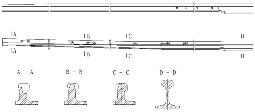
[0028] The super-long point rails of high-speed turnouts are made of special AT rails rolled into standard rail shapes by heel end. The front part is processed by cutting, and the section changes slowly; the rear part is a relatively complete section of AT rail and standard rail, and is processed by driving surface line (rail top and working side). With the gradual widening and heightening of the section size, the contact point gradually shifts from the basic rail to the tip rail when the wheel passes. Schematic diagram of the structure of the super long point rail of the turnout figure 1 shown.

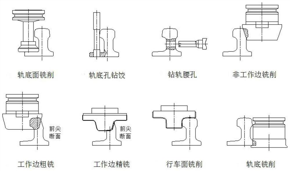
[0029] The following takes CN42# switch point rail as an example to introduce the typical parts and mainstream methods of super-long switch point rail processing. The main structure of other types of point rails is similar. CN42# turnout tip rail processing mainly includes rail bottom milling, rail bottom hole drilling and reaming, rail waist drilling, non-working side rail head mi...


PUM


Abstract

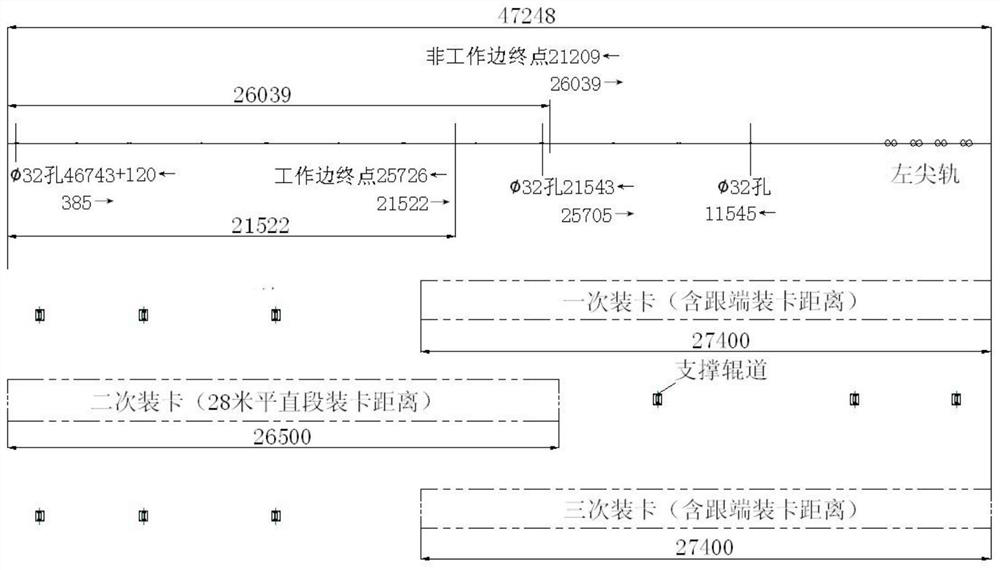
The invention provides a step-by-step machining method of an ultra-long turnout switch rail. An existing short-stroke machine tool is used for performing step-by-step machining on the ultra-long turnout switch rail; and by moving a workpiece and accurately positioning the workpiece, complete continuing of hole drilling and milling is achieved; and the equipment input cost or the switch rail importing cost are substantially lowered.

Description

technical field [0001] The invention relates to the technical field of rail processing, in particular to a step-by-step processing method for super-long switch point rails. Background technique [0002] With the rapid development of passenger high-speed railways in my country, the application of large turnouts is becoming more and more extensive, such as 42#, 50#, 62#, etc. The large turnout has the characteristics of fast locomotive passing speed and comfortable ride. [0003] The ultra-long turnout point rail is one of the main components widely used in high-speed railway turnouts. It has the characteristics of large length specifications, strong bearing capacity, and high precision requirements. To realize the processing of super-long turnout point rails in one clamping process, the stroke of the required machine tool is relatively long. In the past, the finished parts were directly imported or the long-stroke processing equipment was developed. Contents of the inventi...

Claims


Application Information

Patent Timeline
Patent Type & Authority Patents(China)
IPC IPC(8): B23P15/00
CPCB23P15/00
Inventor 王永波
Owner 新铁德奥道岔有限公司
Learn More