Membrane panel forming mold

A technology for forming molds and panels, applied in the field of film panel forming molds, can solve the problems of reducing the production efficiency of film panels, unable to take out the film panels quickly, and low production efficiency of forming molds, etc. Effect

Inactive Publication Date: 2019-08-02
滁州市印科模塑有限责任公司
View PDF6 Cites 1 Cited by
  • Summary
  • Abstract
  • Description
  • Claims
  • Application Information

AI Technical Summary

Problems solved by technology

[0002] The film panel is a plastic product used for identification or protection made of predetermined graphics, text descriptions, etc. on the silk screen of soft plastic materials such as PVC, PC, and PET, and double-sided adhesive tape of different materials. The film panel The use of different materials determines its price and performance. The film panel produced by silk screen printing technology has the biggest feature of clear and intuitive graphics and text, and can adapt to different planes and curved planes. The choice of different materials, PVC, PC, PET and other materials can be used. The film panel has the characteristics of: waterproof, anti-deformation, anti-pollution, high temperature resistance, strong viscosity, etc. At the same time, the service life of the film panel is long. Most of the equipment in the existing technology only uses the film panel Control, in the production process of the film panel, it is necessary to use the film pressing process to complete the film panel in the forming mold, but the production efficiency of the existing forming mold is too low, and the film panel cannot be taken out quickly after forming, and It is also cumbersome to take out the formed panel, which greatly reduces the production efficiency of the film panel

Method used


Image

  • Membrane panel forming mold
  • Membrane panel forming mold
  • Membrane panel forming mold

Examples


Embodiment Construction

[0023] In order to make the technical means, creative features, goals and effects achieved by the present invention easy to understand, the present invention will be further described below in conjunction with specific embodiments.

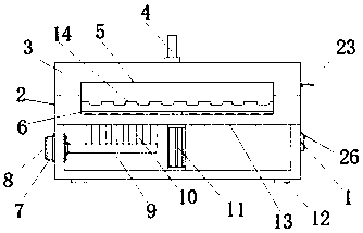
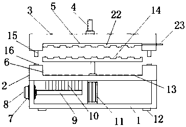
[0024] see Figure 1-5 , the present invention provides a technical solution: a film panel forming mold, including a support frame 1, the four corners of the bottom end of the support frame 1 are fixed with a base 12, the top of the support frame 1 is fixed with a lower membrane shell 2, and the lower mold shell 2 The middle part of the top is provided with a lower mold groove 6, the top of the lower mold shell 2 is placed with an upper mold shell 3, and the middle part of the upper mold shell 3 bottom is provided with an upper mold groove 5, and the inside of the upper mold groove 5 is fixed with an upper template 22. The middle part of the mold shell 3 top is equipped with a rubber injection pipe 4, the bottom end of the support frame 1 inside i...


PUM


Abstract

The invention discloses a membrane panel forming mold. The membrane panel forming mold comprises a supporting frame. The four corners of the bottom end of the supporting frame are all fixedly providedwith bases. The top end of the supporting frame is fixedly provided with a lower mold shell. The middle portion of the top end of the lower mold shell is provided with a lower mold groove. An upper mold shell is placed at the top end of the lower mold shell. The middle portion of the bottom end of the upper mold shell is provided with an upper mold groove. An upper mold plate is fixed to the interior of the upper mold groove. A glue filling pipe is mounted on the middle portion of the top end of the upper mold shell. A push rod motor is fixed to the bottom end of the interior of the supporting frame. An air hood penetrates through the left end of the supporting frame. A rack is connected to the interior of the air hood. A motor is mounted on the rack. According to the membrane panel forming mold, a lower mold plate is connected with a push rod of the push rod motor; after completion of molding, the upper mold shell is opened, the push rod motor can be started to drive the lower mold plate to rise to enable a molded membrane panel to move out of the lower mold groove. The membrane panel forming mold facilitates demolding of the membrane panel, greatly improves the demolding convenience and is suitable for extensive application and popularization.

Description

technical field [0001] The invention relates to a molding die, in particular to a thin film panel molding die. Background technique [0002] The film panel is a plastic product used for identification or protection made of predetermined graphics, text descriptions, etc. on the silk screen of soft plastic materials such as PVC, PC, and PET, and double-sided adhesive tape of different materials. The film panel The use of different materials determines its price and performance. The film panel produced by silk screen printing technology has the biggest feature of clear and intuitive graphics and text, and can adapt to different planes and curved planes. The choice of different materials, PVC, PC, PET and other materials can be used. The film panel has the characteristics of: waterproof, anti-deformation, anti-pollution, high temperature resistance, strong viscosity, etc. At the same time, the service life of the film panel is long. Most of the equipment in the existing technolo...

Claims


Application Information

Patent Timeline
Patent Type & Authority Applications(China)
IPC IPC(8): B29C33/02B29C33/44
CPCB29C33/02B29C33/44
Inventor 李立蔚
Owner 滁州市印科模塑有限责任公司
Why Eureka
Try Eureka