A sas motion compensation method based on delay table correction

A technology of motion compensation and time-delay table, which is applied to radio wave measurement systems, instruments, etc., can solve the problems of long imaging time, increase the calculation amount of imaging processing, etc., and achieve the effect of improving processing efficiency

Active Publication Date: 2021-02-26
HANGZHOU DIANZI UNIV
View PDF4 Cites 0 Cited by
  • Summary
  • Abstract
  • Description
  • Claims
  • Application Information

AI Technical Summary

Problems solved by technology

If the delay table is reconstructed in real time according to the real position of the sonar array at different times, the computational load of the imaging process will be greatly increased, resulting in too long imaging time

Method used


Image

  • A sas motion compensation method based on delay table correction
  • A sas motion compensation method based on delay table correction
  • A sas motion compensation method based on delay table correction

Examples


Embodiment Construction

[0042] The present invention will be further described below in conjunction with the accompanying drawings.

[0043] The specific steps of a motion compensation method based on delay table correction are as follows:

[0044] Step 1. The SAS transmits the chirp signal p R (t) as shown in formula (1):

[0045]

[0046] In the formula (1), "Re ()" means to take the real part, and "exp ()" is an exponential function with the natural constant e=2.71828 as the base, f 0 Is the carrier frequency, K is the modulation frequency, t is the distance up time, T r is the pulse width.

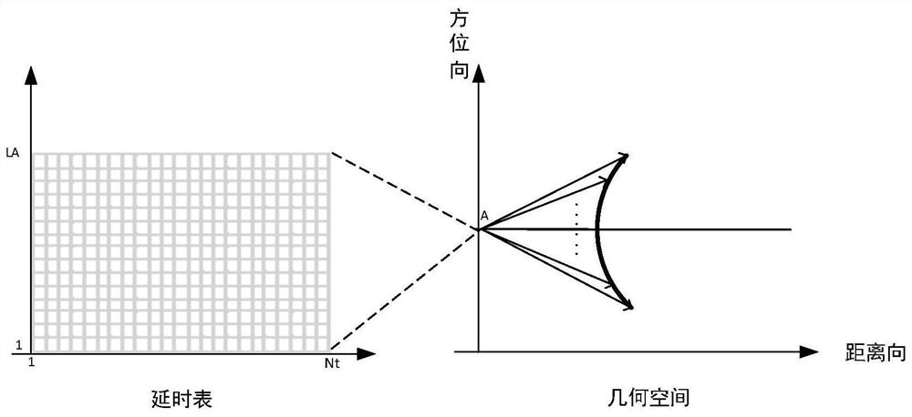
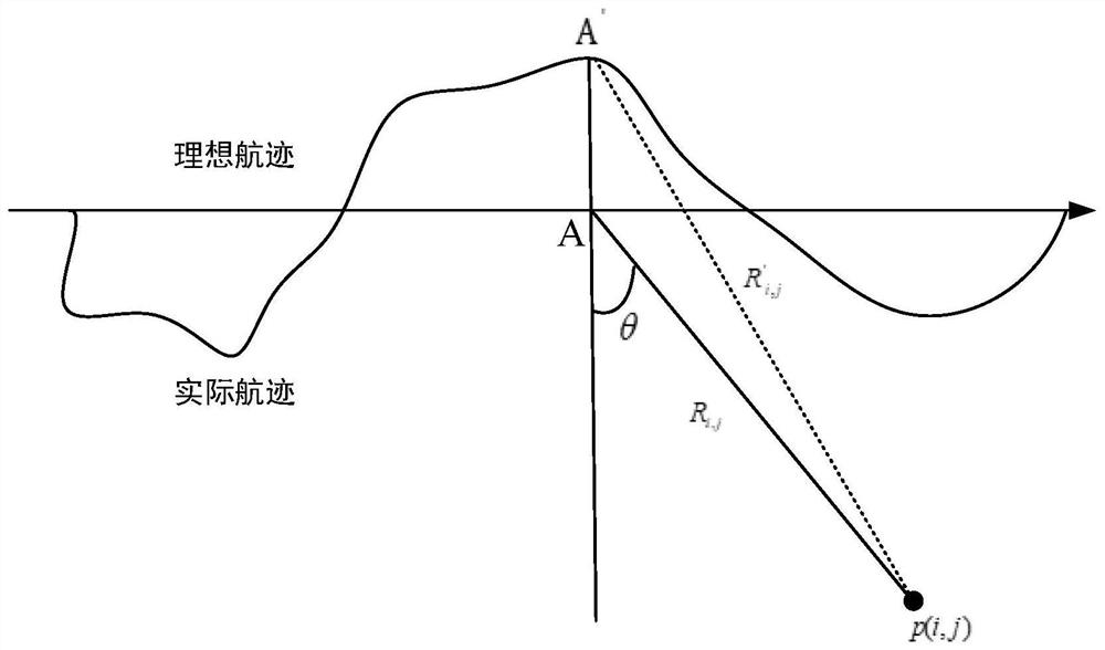
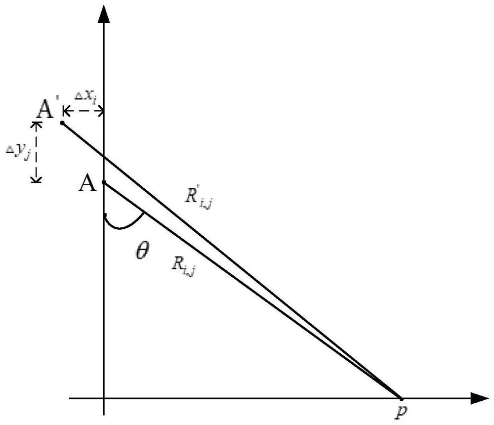
[0047] Under the front and side view, calculate the slant distance R from the ideal emission array position to a certain pixel point (i, j) in the imaging area i,j , as shown in formula (2):

[0048]

[0049] In the formula (2), i=1,2...LA, LA is the number of pixel points in the azimuth direction in the imaging area; j=1,2...Nt, Nt is the number of pixel points in the distance direction in the i...


PUM


Abstract

The invention discloses a SAS motion compensation method based on delay table correction. According to the motion compensation, the invention does not need to recalculate the delay table, and directly converts the pixel points caused by the motion error to the slant distance error of the actual sonar array The delay error is added to the echo delay from the pixel point in the ideal delay table to the ideal sonar array to obtain the actual echo delay and realize motion compensation. This method can avoid the huge amount of computation caused by repeatedly reconstructing the delay table when compensating according to the actual track, and improves the processing efficiency.

Description

technical field [0001] The invention belongs to the field of synthetic aperture sonar signal processing, in particular to a SAS motion compensation method based on delay table correction in a time-domain imaging algorithm. Background technique [0002] Synthetic Aperture Sonar (SAS) utilizes the uniform linear motion of a small-aperture matrix to transmit and receive echo signals in a certain pulse repetition frequency sequence. Coherently process the echo signals at different times and different positions to obtain high-resolution sonar images. [0003] The principle of the time-domain imaging algorithm is to calculate the round-trip time delay between each pixel in the imaging area and the sonar array within the synthetic aperture range. It has the advantages of clear physical meaning and convenient motion compensation, but there are problems such as large amount of calculation and low calculation efficiency. The time-domain imaging algorithm based on the delay table can...

Claims


Application Information

Patent Timeline
Patent Type & Authority Patents(China)
IPC IPC(8): G01S7/539
CPCG01S7/539
Inventor 张福洪江静易志强卓怡琳班多兴陆宇斌贺杰
Owner HANGZHOU DIANZI UNIV
Why Eureka
Try Eureka