
Torpedo for extruder

A torpedo head and extruder technology, applied in the field of extruders, can solve the problem of small mixing effect

Active Publication Date: 2019-08-02
MICHELIN & CO CIE GEN DES ESTAB MICHELIN
View PDF8 Cites 1 Cited by
  • Summary
  • Abstract
  • Description
  • Claims
  • Application Information

AI Technical Summary

Problems solved by technology

In practice, such plates have very little mixing effect on the material to be extruded

Method used


Image

  • Torpedo for extruder
  • Torpedo for extruder
  • Torpedo for extruder

Examples


Embodiment Construction

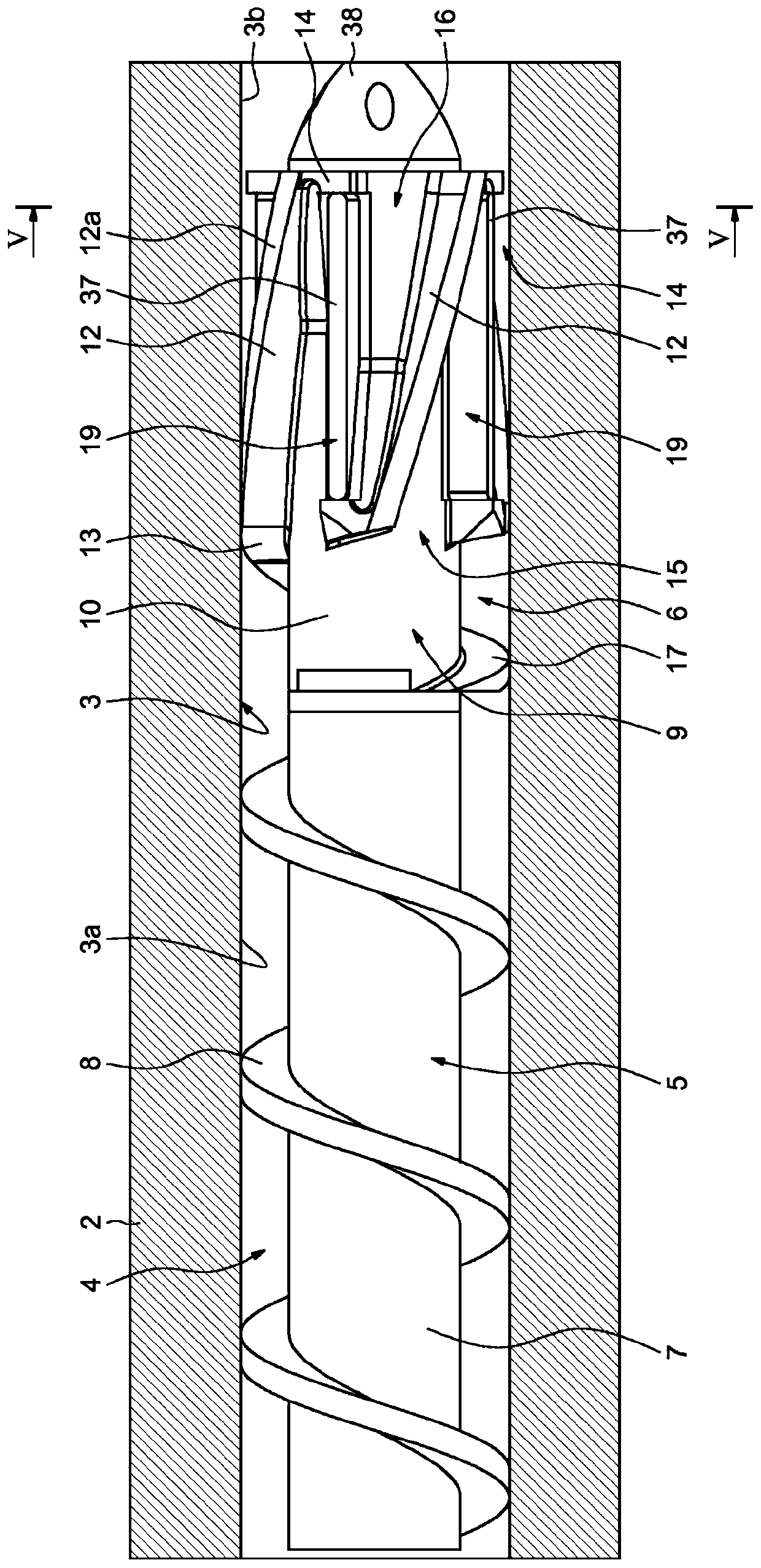
[0029] figure 1 The extruder 1 is partially shown, which includes a longitudinal sheath 2 having a channel 3 with a longitudinal axis, the channel 3 being, for example, cylindrical and extending in a downstream direction. The rotating longitudinal component 4 is installed in the longitudinal channel 3 for driving the material to be extruded in the downstream direction.

[0030] The extruder 1 includes a geared motor (not shown) located upstream for driving the rotating longitudinal assembly 4, an extrusion die (not shown) located downstream of the torpedo head 6 and used to introduce the material to be extruded into Mechanism in longitudinal channel 3 (not shown).

[0031] The rotating longitudinal assembly 4 includes an upstream longitudinal screw 5 and a downstream longitudinal torpedo head 6, the upstream end of the torpedo head 6 is mounted on the downstream end of the screw 5 by a fixing mechanism (not shown). The screw 5 extends in the upstream portion 3a of the longitudinal...


PUM


Abstract

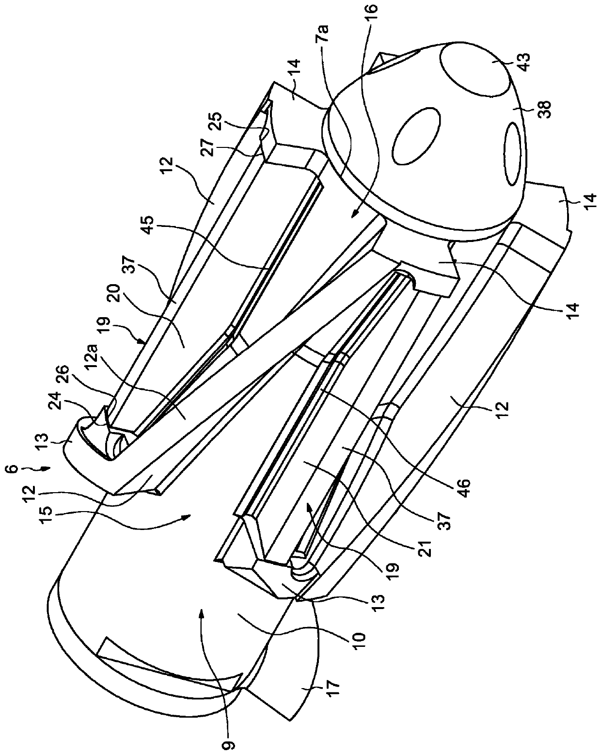
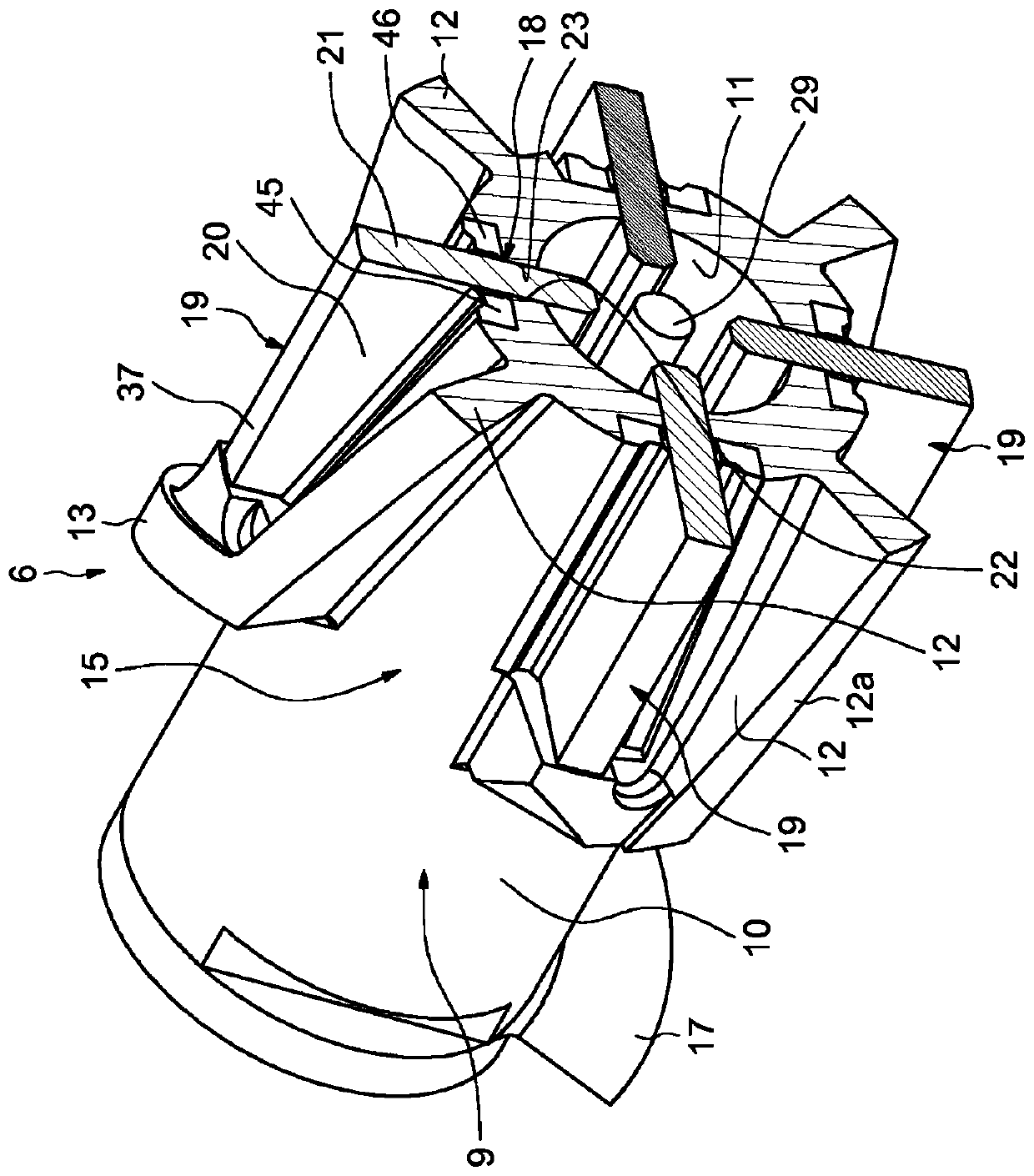
Torpedo for extruder, comprising: a longitudinal body (9) provided at the periphery thereof with a plurality of thread portions (12) protruding outwards and spaced apart in the circumferential direction, a plurality of sluice blades (19) movably mounted on said longitudinal body and partially engaged in slits (18) of said longitudinal body, said longitudinal body (9) and said sluice blades (19) being provided with complementary radial guiding surfaces (13, 14, 18) in contact on one another, and adjustment means (28) for radially moving said sluice blades relative to said longitudinal body. Thesluice blades respectively pass through the spaces between the thread portions. The thread portions (12) and the sluice blades (19) are provided with complementary radial guiding surfaces (13, 14, 18).

Description

Technical field [0001] The invention relates to the field of extruders, in particular to an extruder used to produce profiles through a die. Background technique [0002] Generally, an extruder used for extruding plastic or rubber materials includes a longitudinal sheath, and a longitudinal screw is arranged in the longitudinal sheath, and the longitudinal screw can be rotationally driven so that the material to be extruded is in the direction of the extrusion die Moving in the downstream direction, the channel of the extrusion die determines the cross-section of the profile obtained. [0003] In particular, in the field of rubber compounds in the form of extruded profiles (which can then be used to produce tires), the extrusion screw is provided with a head (usually called a torpedo head) at its downstream end on the side of the die, and the torpedo head is located at Its outer periphery has threads that advance the material and cause mixing or stirring of the rubber mixture (cal...

Claims


Application Information

Patent Timeline
IPC IPC(8): B29C48/505B29C48/67B29C48/70B29B7/40B29C48/565
CPCB29C48/25682B29C48/507B29C48/266B29C48/565B29C48/67B29B7/421B29C2948/92885B29B7/408
Inventor C·贝萨克M·鲁比G·博诺姆
Owner MICHELIN & CO CIE GEN DES ESTAB MICHELIN
Learn More