
Self-adaptive indirect bracket bonding support

A self-adaptive, bracket technology, applied in the direction of the bracket, can solve the problem of small adjustment space and achieve the effect of convenient installation

Active Publication Date: 2019-08-06
张正朴
View PDF9 Cites 0 Cited by
  • Summary
  • Abstract
  • Description
  • Claims
  • Application Information

AI Technical Summary

Problems solved by technology

[0004] The present invention provides self-adaptive indirect brackets for sticking brackets, aiming at the disadvantages of the prior art, such as not being able to adapt well to difficult teeth and having small adjustment space.

Method used


Image

  • Self-adaptive indirect bracket bonding support
  • Self-adaptive indirect bracket bonding support
  • Self-adaptive indirect bracket bonding support

Examples


Embodiment 1

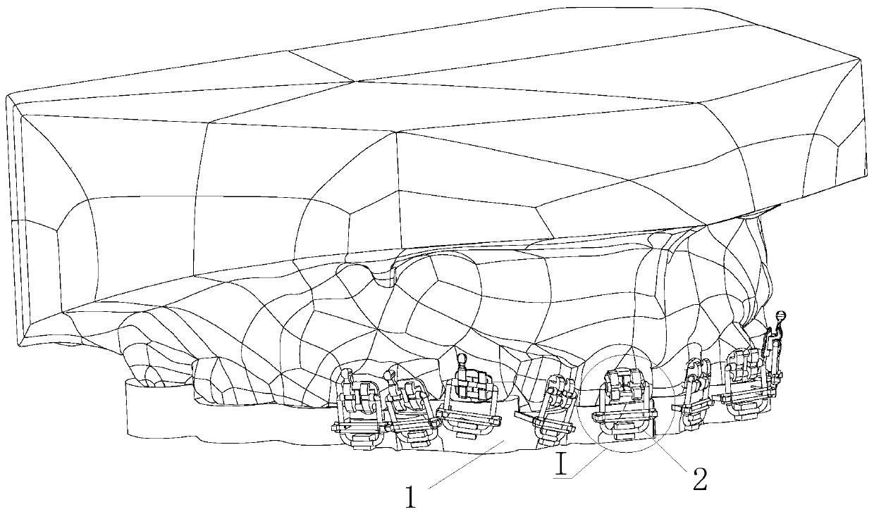
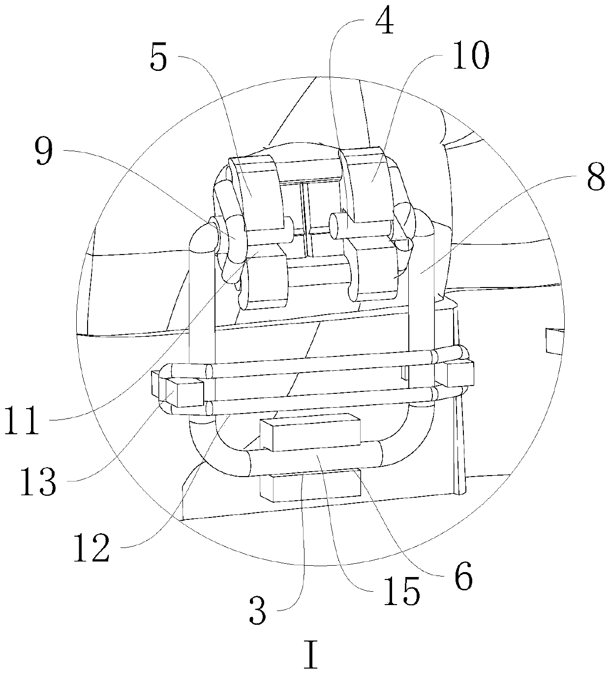
[0029] Such as figure 1 indivual figure 2 As shown, the self-adaptive indirect bracket sticking bracket includes an occlusal plate 1 for occlusion and a positioning spring clip 2 for connecting the occlusal plate 1 and the bracket 5. The occlusal plate 1 is provided with an assembly groove 3 and a positioning spring clip 2 Installed in the assembly groove 3, the positioning spring clip 2 can rotate around the bite plate 1. The occlusal splint 1 is obtained by digital impression taking according to the user's teeth, which is an existing technology and will not be described in detail in this embodiment. The technical solution provided by this embodiment is that the positioning spring clip 2 and the bite plate 1 can rotate around the axis, so that the positioning spring clip 2 is close to or away from the tooth bonding surface. The bracket 5 installed on the positioning spring clip 2 can support the bracket 5, and the bracket 5 can rotate around the positioning spring clip 2 a...

Embodiment 2

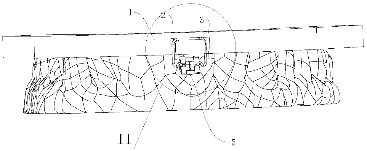
[0039] Such as image 3 and Figure 4 As shown, this embodiment also provides an adaptive indirect bracket sticking bracket, the difference from Embodiment 1 is that the installation groove is an inverted U-shaped groove, and the installation groove is opened on the outside of the occlusal plate 1 on the side. The mounting groove 3 includes a first mounting groove 6 in the horizontal direction and a side groove 7 that forms a U-shaped groove with the first mounting groove 6 on both sides of the first mounting groove 6. The first mounting groove 6 is arranged in a horizontal direction. It should be noted that Whether the first installation groove 6 is horizontal needs to be related to the installation angle of the bracket 5, and the level here is not a limitation of this solution, because it can also be inclined upward or downward according to actual needs. The rotating shaft 15 is connected to the card shaft 4 through a connecting rod 8, and the connecting rod 8 is arranged ...

Embodiment 3

[0041] Such as Figure 5 As shown, this embodiment also provides an adaptive indirect bracket sticking bracket, which differs from Embodiment 2 in that no bending portion 14 is preset on the clamping shaft 4, and the clamping shaft 4 is an optical axis.


PUM


Abstract

The invention relates to the field of bracket bonding, and discloses a self-adaptive indirect bracket bonding support comprising an occlusal plate (1) for occlusion and a positioning spring clip (2) for connecting the occlusal plate (1) and a bracket (5), an assembly groove (3) is arranged on the occlusal plate (1), the positioning spring clip (2) is arranged in the assembly groove (3), and the positioning spring clip (2) can rotate around the occlusal plate (1). The self-adaptive indirect bracket bonding support also includes the bracket (5); the bracket (5) includes a ligating wing (10) andan arch wire trench (11); the positioning spring clip (2) comprises a rotating shaft (15) and a clamp shaft (4) for being connected with the bracket (5), the assembly groove (3) comprises a first mounting groove (6) connected with a rotating shaft (15); the clamp shaft (4) is assembled in the arch wire groove (11) and is rotatingly connected with the bracket (5). The support has the advantages ofconvenient adjustment and can adapt to different tooth types.

Description

technical field [0001] The invention relates to the field of bracket pasting, in particular to an adaptive indirect bracket pasting bracket. Background technique [0002] At present, in the process of orthodontic treatment of oral teeth, the orthodontic bracket is fixed on the tooth surface, and the archwire passes through the archwire groove (also known as the square wire groove) on the bracket, and is connected by a ligature rubber ring or a ligature wire. The steel wire directly ligates the arch wire to the arch wire groove of the bracket, and the correction force of the arch wire is transmitted to the teeth through the bracket, so that the teeth move as expected to achieve the purpose of orthodontics. Therefore, the bracket has strict requirements on the sticking position on the teeth, because this is an important factor affecting the correction effect. There are two ways to choose the position of the traditional bracket paste, one is to mark on the teeth according to e...

Claims


Application Information

Patent Timeline
Patent Type & Authority Applications(China)
IPC IPC(8): A61C7/14A61C7/16
CPCA61C7/146A61C7/16
Inventor 张正朴
Owner 张正朴
Learn More