Milling machine for manufacturing precision parts with adjustable depth and angle of milling cutter

A technology of milling cutter depth and precision parts, which is applied in the field of milling machines, can solve problems such as inability to adjust, increase costs, and errors, and achieve the effects of improving angle machining accuracy, reducing material loss, and reducing manufacturing costs

Inactive Publication Date: 2020-06-30
武汉威立信科技有限公司
View PDF6 Cites 0 Cited by
  • Summary
  • Abstract
  • Description
  • Claims
  • Application Information

AI Technical Summary

Problems solved by technology

[0003] Most of the milling cutters of the existing milling machines are fixedly installed on the milling cutter head, so that the length and inclination angle of the installed milling cutter are fixed parameters and cannot be adjusted, so that there will be errors in the milling of the milling cutter. For precision parts Said that milling is very strict, such as 1mm plus or minus how many microns have precision requirements, if the size is wrong, it will become a waste product, which is equivalent to reprocessing, which is time-consuming and laborious, and sometimes even the entire processing material will be scrapped. This results in an increase in cost

Method used

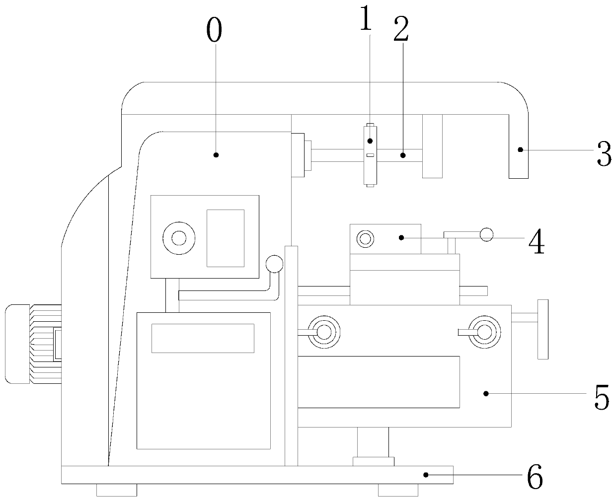
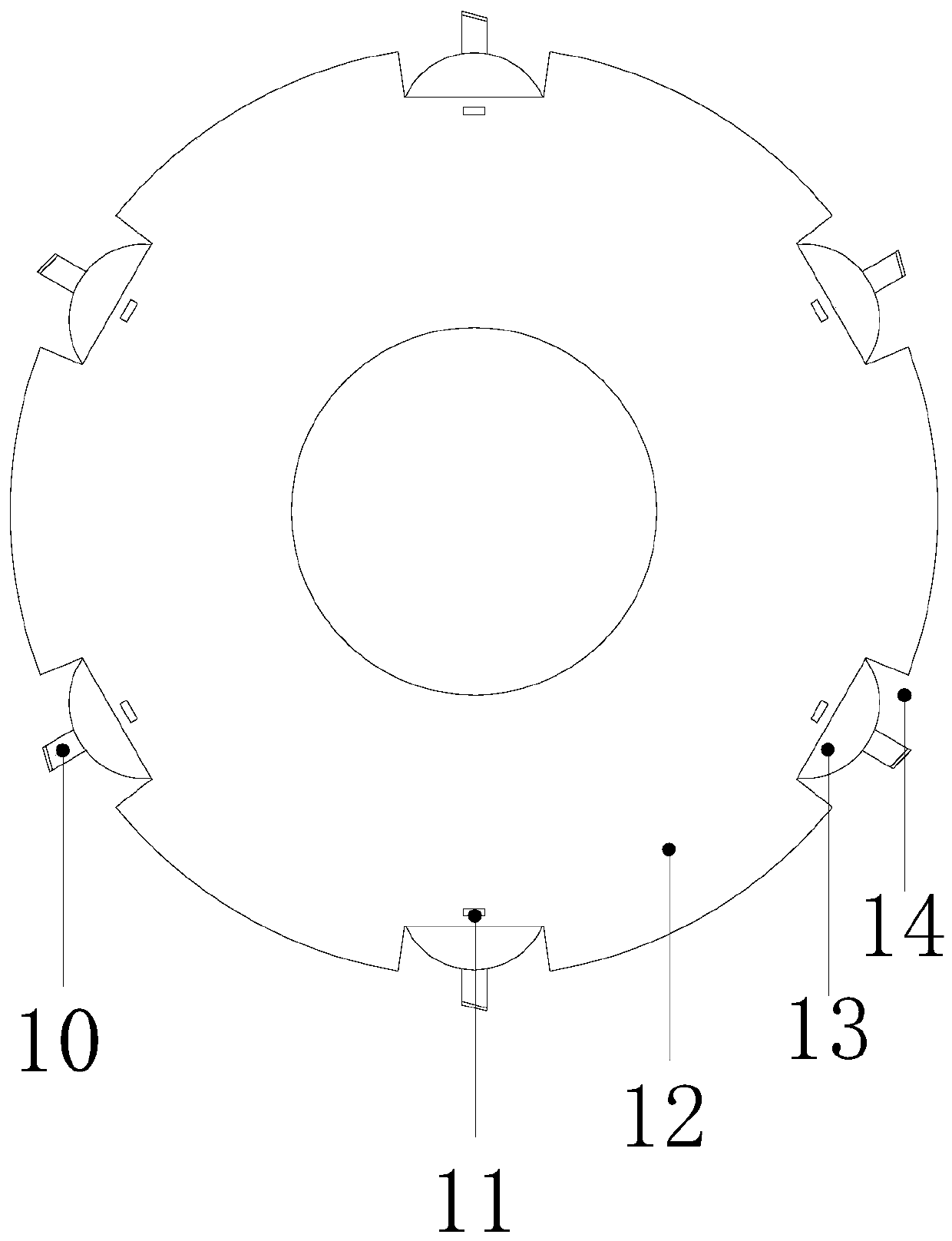
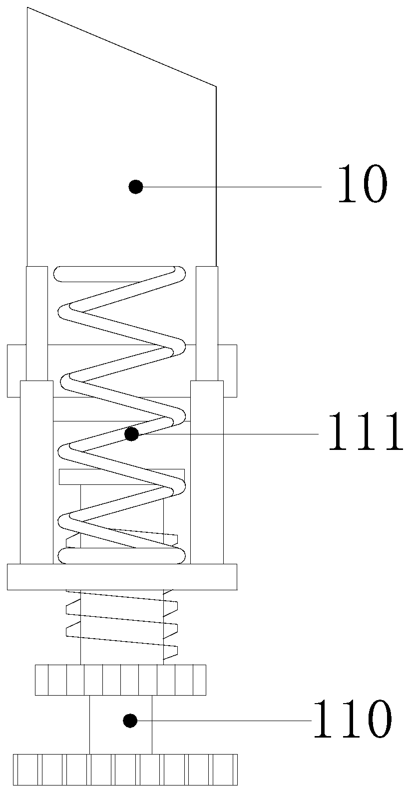

Image

  • Milling machine for manufacturing precision parts with adjustable depth and angle of milling cutter
  • Milling machine for manufacturing precision parts with adjustable depth and angle of milling cutter
  • Milling machine for manufacturing precision parts with adjustable depth and angle of milling cutter

Examples


Embodiment Construction

[0030] The following will clearly and completely describe the technical solutions in the embodiments of the present invention with reference to the accompanying drawings in the embodiments of the present invention. Obviously, the described embodiments are only some, not all, embodiments of the present invention. Based on the embodiments of the present invention, all other embodiments obtained by persons of ordinary skill in the art without making creative efforts belong to the protection scope of the present invention.

[0031] In the description of the present invention, it should be noted that unless otherwise specified and limited, the terms "connected" and "connected" should be understood in a broad sense, for example, it can be a fixed connection, a detachable connection, or an integral Ground connection; it can be mechanical connection or electrical connection; it can be direct connection or indirect connection through an intermediary. Those of ordinary skill in the art ...


PUM


Abstract

The invention discloses a milling machine with the milling cutter depth and angle adjustability for precision components. The milling machine with the milling cutter depth and angle adjustability forthe precision components structurally comprises a machine body, a milling cutter device, a main shaft, a cantilever, a working table, a lifting table and a base, wherein the base is connected to the bottom part of the machine body; and the cantilever is fixed to the top part of the machine body. Compared with the prior art, the milling machine with the milling cutter depth and angle adjustabilityfor the precision components provided by the invention has the beneficial effects that when a spring is stressed, the space between spring rings can be equidistantly increased or reduced, so that themilling cutter has a flexible adjusting function, the demand on different processing depths of the precision components can be met, and the precision of the processing depths is improved; a small geardrives a middle gear to rotate, the middle gear drives a big gear to rotate, so that the precision in angle adjustment is greatly improved; an angle rotating plate can rotate by adopting a circle center as an axis, so that the occurrence of the phenomenon that the angle rotating plate exceeds a groove so as to cause the obstruction on processing the precision components through the milling cutteris effectively prevented; and the milling cutter have an angle adjusting function so as to meet the demands on different angles during precision component processing, so that the angle processing precision is improved, the material loss is reduced, and the manufacturing cost is reduced.

Description

technical field [0001] The invention relates to the technical field of milling machines, in particular to a milling machine for manufacturing precision parts with adjustable depth and angle of milling cutters. Background technique [0002] A milling machine is a machine tool that uses a milling cutter to process various surfaces of a workpiece. Generally, the milling cutter mainly moves in the form of rotational motion, and the movement of the workpiece and the milling cutter is a feed motion, so as to process planes, grooves, etc. of the workpiece. Wait. [0003] Most of the milling cutters of the existing milling machines are fixedly installed on the milling cutter head, so that the length and inclination angle of the installed milling cutter are fixed parameters and cannot be adjusted, so that there will be errors in the milling of the milling cutter. For precision parts Said that milling is very strict, such as 1mm plus or minus how many microns have precision requireme...

Claims


Application Information

Patent Timeline
Patent Type & Authority Patents(China)
IPC IPC(8): B23C1/027B23C5/08B23Q1/26
CPCB23C1/027B23C5/08B23Q1/26
Inventor 张林
Owner 武汉威立信科技有限公司
Why Eureka
Try Eureka