Double-sided milling machine

A milling machine, double-sided technology, applied in the field of milling machines, to achieve the effect of strong practicability, increasing stability and structural strength, and overcoming the overturning moment

Pending Publication Date: 2018-12-14
芜湖龙鳞汽车部件有限公司
View PDF2 Cites 0 Cited by
  • Summary
  • Abstract
  • Description
  • Claims
  • Application Information

AI Technical Summary

Problems solved by technology

[0005] Although the milling machines involved in the above comparative documents have solved the corresponding practical problems, they have not solved the problems raised by this application very well. Therefore, the milling machines need to be redesigned more reasonably

Method used


Image

  • Double-sided milling machine
  • Double-sided milling machine

Examples


Embodiment 1

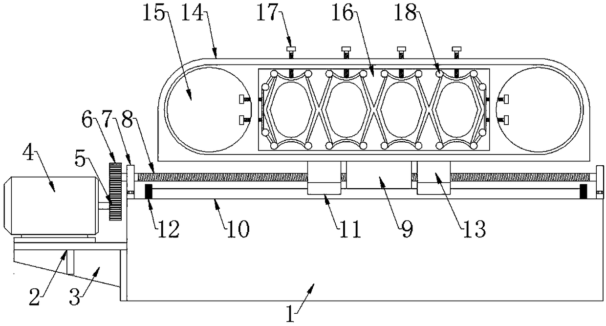
[0021] Such as Figure 1 to Figure 2 As shown, a double-sided milling machine includes a workpiece fixing device and a workpiece milling device, and the workpiece milling device is symmetrically arranged on both sides of the workpiece fixing device,

[0022] The workpiece fixing device includes a support platform-1 and a servo motor 4, the servo motor 4 is horizontally installed on the front end surface of the support platform-1 through the motor fixing plate-2, and a gear-1 is installed at the end of the rotating shaft of the servo motor 4. 5. The gear 2 6 is meshed above the gear 1 5, the gear 2 6 is mounted on the front end of the screw 1 8, and the screw 1 8 is horizontally installed on the upper end surface of the support table 1 1 through the bearing seat 1 7 , said leading screw one 8 is threadedly connected with slide block one 9, the upper end of said slide block one 9 is equipped with support frame 14, and the left and right sides of the bottom of said support frame ...

Embodiment 2

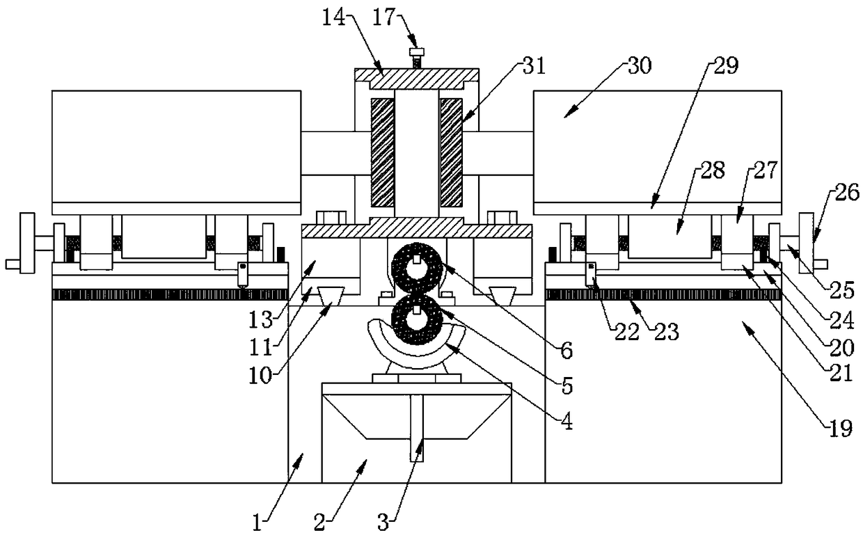
[0026] Such as Figure 1 to Figure 2 As shown, a double-sided milling machine includes a workpiece fixing device and a workpiece milling device, and the workpiece milling device is symmetrically arranged on both sides of the workpiece fixing device,

[0027] The workpiece fixing device includes a support platform-1 and a servo motor 4, the servo motor 4 is horizontally installed on the front end surface of the support platform-1 through the motor fixing plate-2, and a gear-1 is installed at the end of the rotating shaft of the servo motor 4. 5. The gear 2 6 is meshed above the gear 1 5, the gear 2 6 is mounted on the front end of the screw 1 8, and the screw 1 8 is horizontally installed on the upper end surface of the support table 1 1 through the bearing seat 1 7 , said leading screw one 8 is threadedly connected with slide block one 9, the upper end of said slide block one 9 is equipped with support frame 14, and the left and right sides of the bottom of said support frame ...


PUM


Abstract

The invention discloses a double-sided milling machine, and relates to the technical field of milling machines. The double-sided milling machine comprises a workpiece fixing device and workpiece milling devices, and the workpiece milling devices are symmetrically arranged on two sides of the workpiece fixing device. The workpiece fixing device comprises a first supporting platform and a servo motor, a first gear is installed at the tail end of a rotating shaft of the servo motor, a second gear is arranged above the first gear in a meshing mode, and the second gear is installed at the front endof a first lead screw. A first sliding block is connected to the first lead screw in a threaded mode, a supporting frame is installed at the upper end of the first sliding block, and a placement frame is arranged on the supporting frame. The workpiece milling devices comprise second supporting platforms and milling cutter driving motors, the second supporting platforms are provided with second bearing seats and second lead screws, fourth sliding blocks are connected to the second lead screws in a threaded mode, second motor fixing plates are installed at the upper ends of the fourth sliding blocks, and the second motor fixing plates are provided with milling cutter driving motors and milling cutters are installed at the tail ends of rotating shafts of the milling cutter driving motors. The double-sided milling machine puts workpieces in the placement frame in the workpiece fixing device and then performs the milling operation through the milling cutters of the workpiece milling devices.

Description

technical field [0001] The invention relates to the technical field of milling machines, in particular to a double-sided milling machine. Background technique [0002] Milling machines mainly refer to machine tools that use milling cutters to process various surfaces of workpieces. It can process planes, grooves, various curved surfaces, gears, etc. The milling machine is a machine tool with a wide range of uses. It can process planes, grooves, toothed parts, spiral surfaces and various curved surfaces on the milling machine. In addition, it can also be used to process the surface and inner hole of the rotating body and perform cutting work. When the milling machine is working, the workpiece is installed on the worktable or the accessories such as the indexing head. The main movement of the milling cutter is the rotation, supplemented by the feed movement of the worktable or the milling head, and the workpiece can obtain the required processing surface. But it is such a m...

Claims


Application Information

Patent Timeline
IPC IPC(8): B23C1/04B23Q5/36B23Q5/40B23Q1/01
CPCB23C1/045B23Q1/017B23Q5/36B23Q5/40
Inventor 胡万胜朱统坤宇宙凌静
Owner 芜湖龙鳞汽车部件有限公司
Why Eureka
Try Eureka