A Tooling Equipment Facilitating Precise Positioning

A tooling equipment and precise positioning technology, applied in the field of machining, can solve problems such as difficulty in ensuring accurate positioning, achieve high coaxiality and achieve the effect of precise positioning

Active Publication Date: 2021-03-23
霍山嘉远智能制造有限公司
View PDF6 Cites 0 Cited by
  • Summary
  • Abstract
  • Description
  • Claims
  • Application Information

AI Technical Summary

Problems solved by technology

[0003] The purpose of the present invention is to solve the disadvantages in the prior art that it is difficult to ensure accurate positioning when the coaxiality of both ends of the workpiece is required to be below 0.05 mm, and propose a tooling device that facilitates precise positioning

Method used


Image

  • A Tooling Equipment Facilitating Precise Positioning
  • A Tooling Equipment Facilitating Precise Positioning
  • A Tooling Equipment Facilitating Precise Positioning

Examples


Embodiment 1

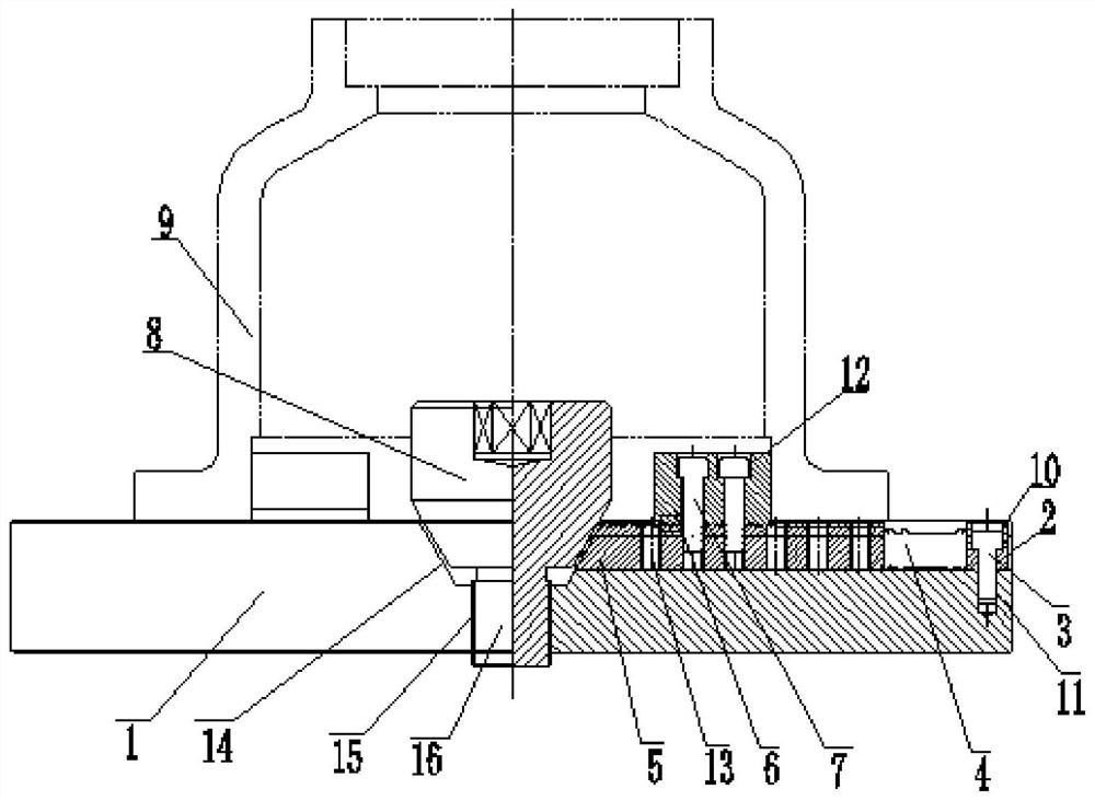
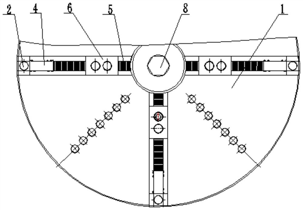
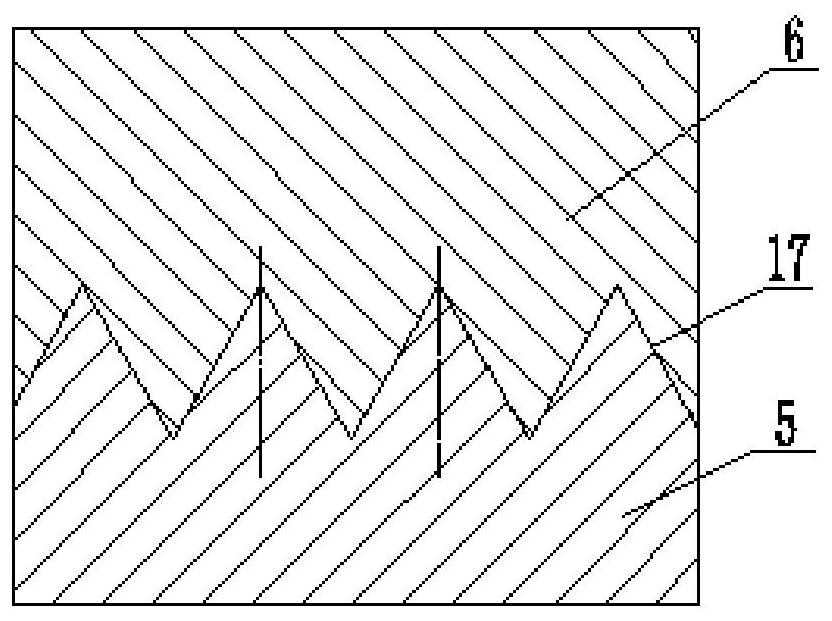
[0027] refer to Figure 1-6 , a tooling device convenient for precise positioning, including a faceplate 1, a part 9 is provided on the top side of the faceplate 1, a tapered groove 14 is opened on the top side of the faceplate 1, and a taper adjustment block 8 is movably installed in the tapered groove 14, and the cone The inner wall of the bottom side of the shape groove 14 is provided with a fixed groove 15, and the bottom side of the taper adjustment block 8 is fixedly equipped with a fixed column 16. T-shaped rack slider 5, one side of the T-shaped rack slider 5 is in contact with one side of the taper adjustment block 8, and the top side of the T-shaped rack slider 5 is movably installed with a positioning block 6, and the positioning block 6 One side is in contact with the inner wall of one side of the part 9, one side of the T-shaped rack slider 5 is fixedly installed with one end of the tension spring 4, and the other end of the tension spring 4 is fixedly installed w...

Embodiment 2

[0038] refer to Figure 1-6 , refer to Figure 1-5 , a tooling device convenient for precise positioning, including a faceplate 1, a part 9 is provided on the top side of the faceplate 1, a tapered groove 14 is opened on the top side of the faceplate 1, and a taper adjustment block 8 is movably installed in the tapered groove 14, and the cone The bottom side inner wall of shaped groove 14 is provided with fixed groove 15, and the bottom side of taper adjustment block 8 is fixedly installed with fixed column 16 by welding, and the bottom end of fixed column 16 extends in the fixed groove 15, and the top side of faceplate 1 is provided with Four T-shaped rack sliders 5, one side of the T-shaped rack slider 5 is in contact with one side of the taper adjustment block 8, and a positioning block 6 is installed on the top side of the T-shaped rack slider 5, and the positioning block One side of 6 is in contact with the inner wall of one side of part 9, one side of T-shaped rack slid...


PUM


Abstract

The invention belongs to the field of mechanical processing, especially a kind of tooling equipment that is convenient for precise positioning. Aiming at the existing problem that it is difficult to ensure accurate positioning when the coaxiality of both ends of the workpiece is required to be below 0.05 mm, the following proposal is now proposed, It includes a faceplate, the top side of the faceplate is provided with parts, the top side of the faceplate is opened with a tapered groove, and a taper adjustment block is installed in the tapered groove, and a fixed groove is opened on the inner wall of the bottom side of the tapered groove to adjust the taper. The bottom side of the block is fixedly installed with a fixed column, and the bottom end of the fixed column extends into the fixed groove. Four T-shaped rack sliders are arranged on the top side of the faceplate, and one side of the T-shaped rack slider is adjusted with the taper. One side of the block is in contact, and a positioning block is movably installed on the top side of the T-shaped rack slider. In the present invention, by moving the taper adjustment block, the gap adjustment between the positioning block and the inner hole of the part can be realized, precise positioning can be realized, and the requirement of high coaxiality at both ends can be guaranteed.

Description

technical field [0001] The invention relates to the technical field of mechanical processing, in particular to a tooling device convenient for precise positioning. Background technique [0002] In the field of machining, when the product must be reversed and the coaxiality of both ends is very high, generally one end is processed first, and the tolerance of a certain size of the inner hole is changed to a smaller size, which is set as the process size. When processing the other end The hole of this process size will be used for positioning, but in any case, there will be a gap between the process hole and the positioning pin. It can be guaranteed if the coaxiality of both ends is not too high, but the coaxiality of both ends is required to be 0.05mm It is difficult to guarantee the following. Contents of the invention [0003] The purpose of the present invention is to solve the disadvantages in the prior art that it is difficult to ensure accurate positioning when the co...

Claims


Application Information

Patent Timeline
Patent Type & Authority Patents(China)
IPC IPC(8): B23Q3/06B23K37/04
CPCB25B11/00
Inventor 万继升杜应流杜坤王坤桂琦吕晟曾科
Owner 霍山嘉远智能制造有限公司
Why Eureka
Try Eureka