
Automatic transfer equipment based on hydraulic cylinder assembly line

An assembly line and hydraulic cylinder technology, applied in the field of hydraulic cylinder manufacturing, can solve the problems of high labor intensity, messy placement, heavy weight, etc., and achieve the effect of saving labor, neat placement, and quick installation.

Pending Publication Date: 2019-08-06
BENGBU YELI MACHINERY
View PDF0 Cites 0 Cited by
  • Summary
  • Abstract
  • Description
  • Claims
  • Application Information

AI Technical Summary

Problems solved by technology

[0002] At present, with the development of automation control, the automatic assembly of products is becoming more and more mature. The automatic assembly line of hydraulic cylinders has effectively solved a series of problems such as high labor intensity, low efficiency, and unstable quality of manual assembly of hydraulic cylinders. The automatic transfer of the assembled hydraulic cylinder to the material rack has become another problem that plagues the enterprise
The cost of using industrial robots is high, and the requirements for material racks are high. Many companies use manual handling of the assembled hydraulic cylinders to the material racks. This process will inevitably increase the labor intensity of workers, and the weight of a single product of the hydraulic cylinder is heavy and easy to carry manually. Cause bumps and messy placement, and cannot make good use of the advantages of automatic assembly lines

Method used


Image

  • Automatic transfer equipment based on hydraulic cylinder assembly line
  • Automatic transfer equipment based on hydraulic cylinder assembly line
  • Automatic transfer equipment based on hydraulic cylinder assembly line

Examples


Embodiment Construction

[0022] The following will clearly and completely describe the technical solutions in the embodiments of the present invention with reference to the accompanying drawings in the embodiments of the present invention. Obviously, the described embodiments are only some, not all, embodiments of the present invention. Based on the embodiments of the present invention, all other embodiments obtained by persons of ordinary skill in the art without making creative efforts belong to the protection scope of the present invention.

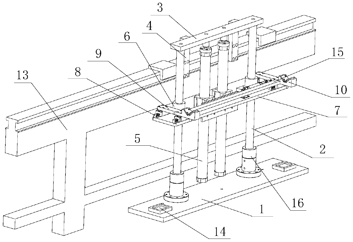
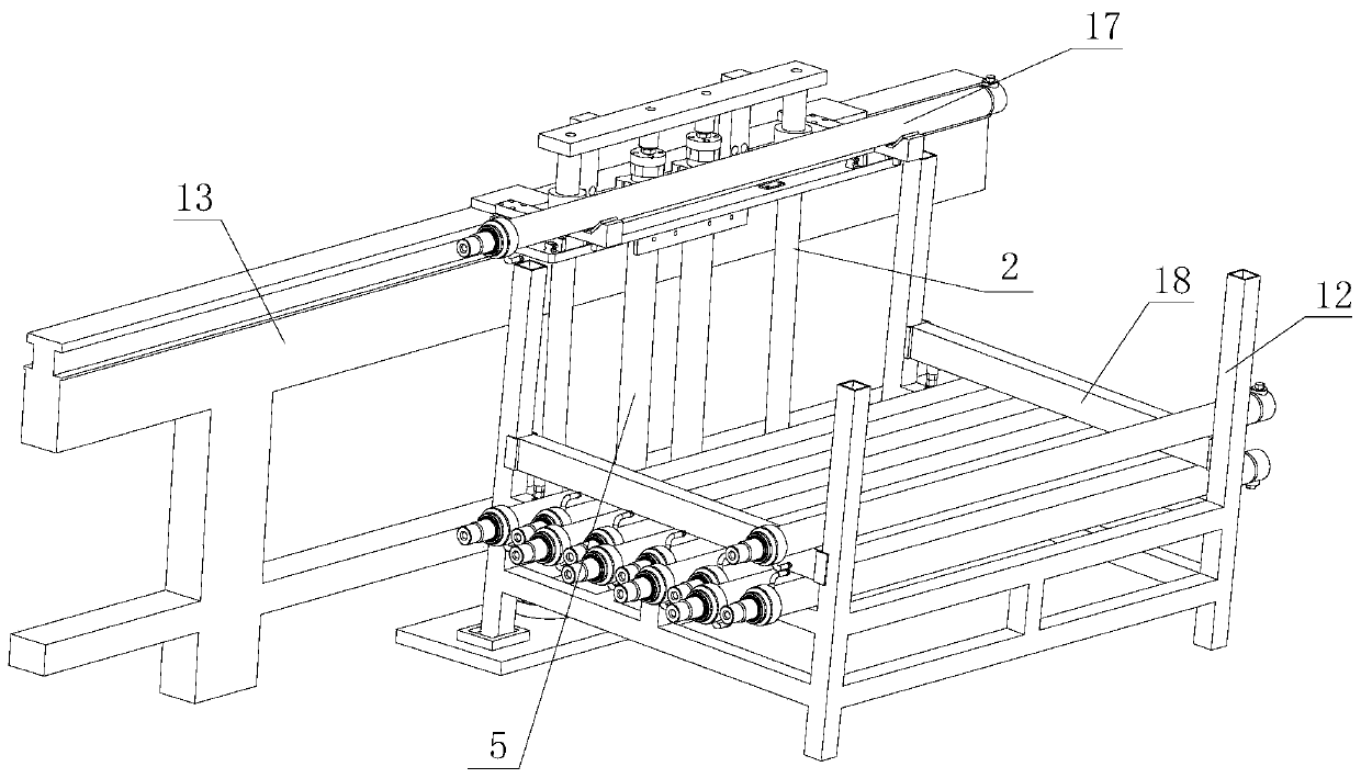
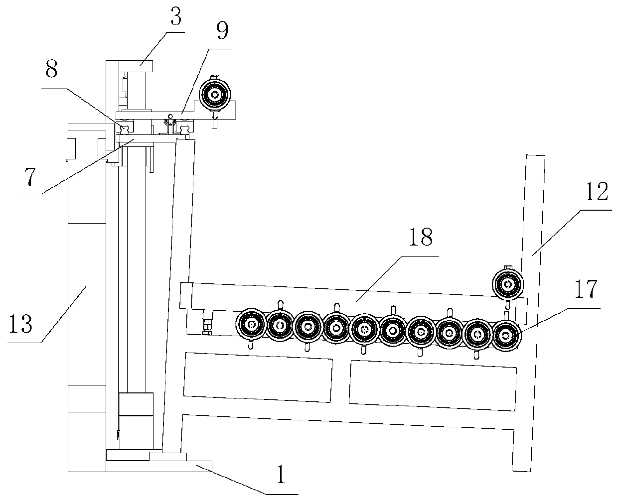
[0023] See Figure 1-Figure 4 , the automatic transfer equipment based on the hydraulic cylinder assembly line, including a bottom plate 1, two lifting guide rails 2 fixed on the bottom plate 1, a top plate 3 fixedly connected to the top of the lifting guide rail 2, connected to the top plate 3 and vertically arranged The connecting plate 4, two rodless cylinders 5 located between the two lifting guide rails 2 and whose top ends are fixedly connected to the to...


PUM


Abstract

The invention discloses automatic transfer equipment based on a hydraulic cylinder assembly line. The automatic transfer equipment comprises a bottom plate, two lifting guide rails, a top plate, a connecting plate, a rodless air cylinder, sliding sleeves, mounting plates, side moving guide rails, dragging rods, V-shaped supporting blocks and side moving air cylinders, wherein the two lifting guiderails are fixed at the bottom end of the bottom plate, the top plate is fixedly connected to the top ends of the lifting guide rails, the connecting plate is connected to the top plate and verticallyarranged, the rodless air cylinder is located between the two lifting guide rails, the top end of the rodless air cylinder is fixedly connected to the top plate, the lifting guide rails are sleeved with the sliding sleeves and the mounting plates in a sliding mode correspondingly, the side moving guide rails are fixed to the upper end faces of the mounting plates correspondingly, the dragging rods are arranged on the side moving guide rails in a sliding mode, and the V-shaped supporting blocks are fixed to the outer ends of the dragging plates and provided with upward V-shaped slots. The equipment is simple in structure, convenient to install and capable of being quickly installed with an assembly line so as to automatically transfer hydraulic cylinders to a material rack, and has low requirements on the structure and positioning of the material rack. By means of the equipment, the hydraulic cylinders are automatically transferred from the assembly line to the material rack, the laborforce of manual transportation is omitted, collision is avoided, and the hydraulic cylinders are placed in order.

Description

technical field [0001] The invention relates to the field of hydraulic cylinder manufacturing, specifically an automatic transfer device based on a hydraulic cylinder assembly line. Background technique [0002] At present, with the development of automation control, the automatic assembly of products is becoming more and more mature. The automatic assembly line of hydraulic cylinders has effectively solved a series of problems such as high labor intensity, low efficiency, and unstable quality of manual assembly of hydraulic cylinders. The automatic transfer of the assembled hydraulic cylinder to the material rack has become another problem that plagues the enterprise. The cost of using industrial robots is high, and the requirements for material racks are high. Many companies use manual handling of the assembled hydraulic cylinders to the material racks. This process will inevitably increase the labor intensity of workers, and the weight of a single product of the hydraulic...

Claims


Application Information

Patent Timeline
Patent Type & Authority Applications(China)
IPC IPC(8): B23P19/00
CPCB23P19/001B23P19/004
Inventor 孙鸿钧宋西华陈禄周宗恩王占辉钱老红张勇段忠全沈露露朱明杨童文强
Owner BENGBU YELI MACHINERY
Learn More