
Automatic ink box sealing device

A sealing device and ink cartridge technology, applied in packaging, transportation packaging, transportation and packaging, etc., can solve the problems of uneven sealing surface, easy folding, waste of aluminum film materials, etc., to improve efficiency and sealing effect, stability and Good reliability, saving manpower and material resources

Pending Publication Date: 2019-08-06
北海绩迅科技股份有限公司
View PDF0 Cites 1 Cited by
  • Summary
  • Abstract
  • Description
  • Claims
  • Application Information

AI Technical Summary

Problems solved by technology

The whole production process is relatively cumbersome, and the current production requires a lot of manual labor to complete each process of ink cartridge production on the ink cartridge production line. This production method not only requires a large number of people, but also the continuous operation of the assembly line greatly increases the fatigue of the staff. Further, the production efficiency of the ink cartridge is unsatisfactory. In addition, before the artificial use of aluminum film material to seal the ink cartridge, the aluminum film in roll shape needs to be conveyed and cut, because the aluminum film is prone to slipping and warping during the transportation process. In addition, the specifications of the aluminum film itself, such as thickness, will also have a certain impact on its own transport stability. For example, the thinner aluminum film is more flexible and prone to folding, which leads to poor transport stability of the aluminum film. The cutting position of the aluminum film is inaccurate, resulting in a waste of aluminum film material, and it will also lead to uneven sealing surface after the ink cartridge is sealed, and poor sealing effect of the ink cartridge

Method used


Image

  • Automatic ink box sealing device
  • Automatic ink box sealing device
  • Automatic ink box sealing device

Examples


Embodiment 1

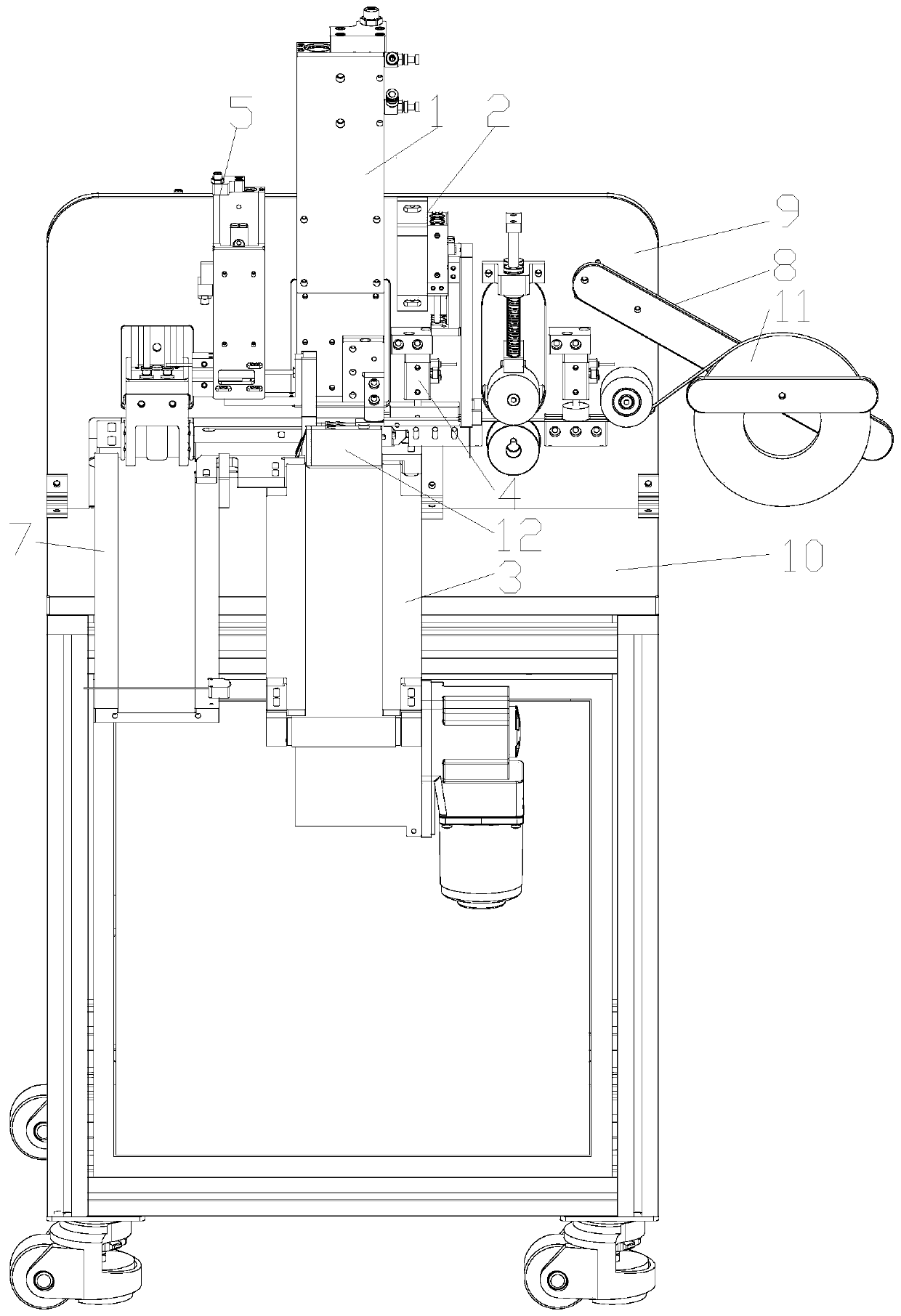
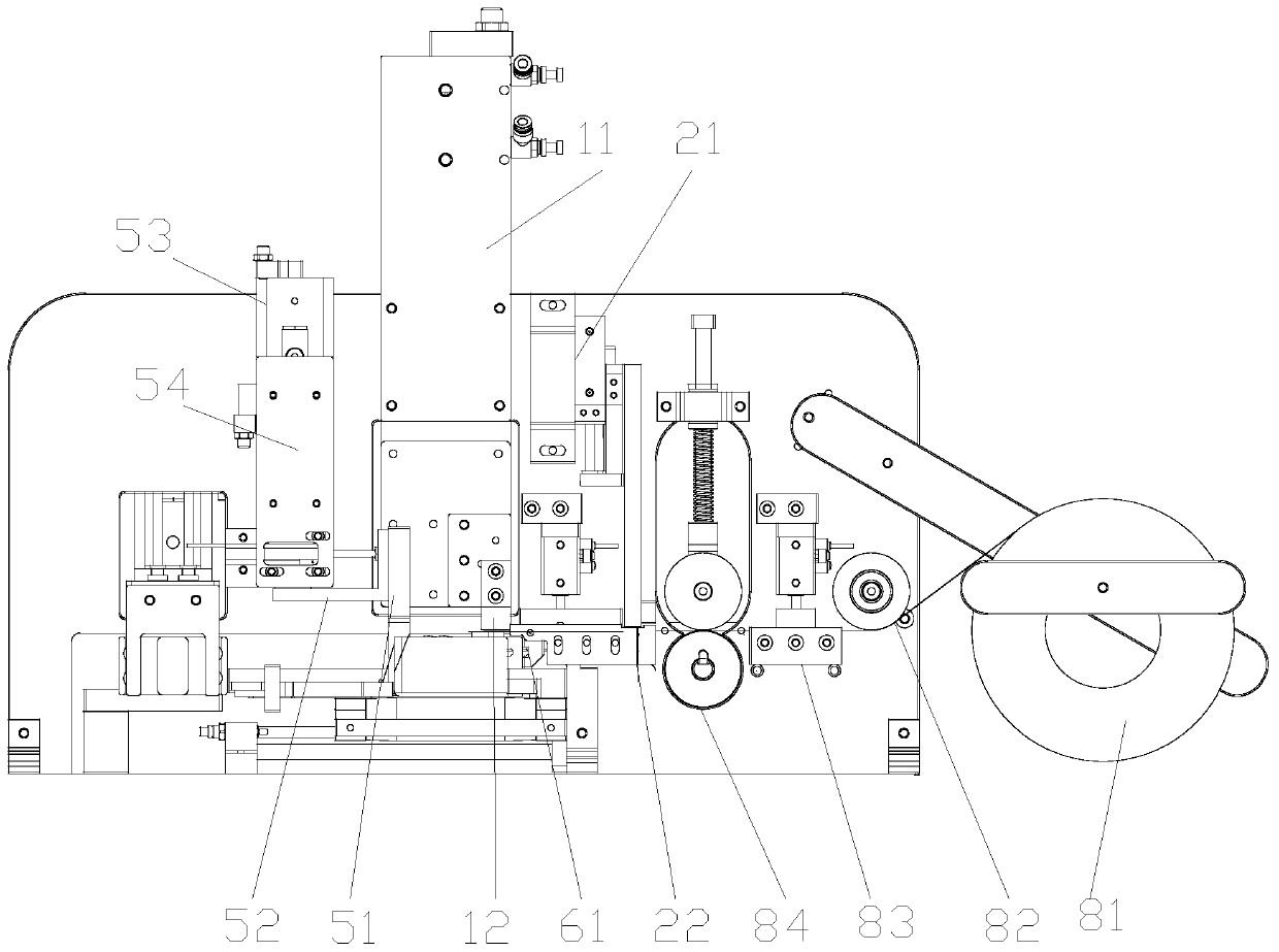
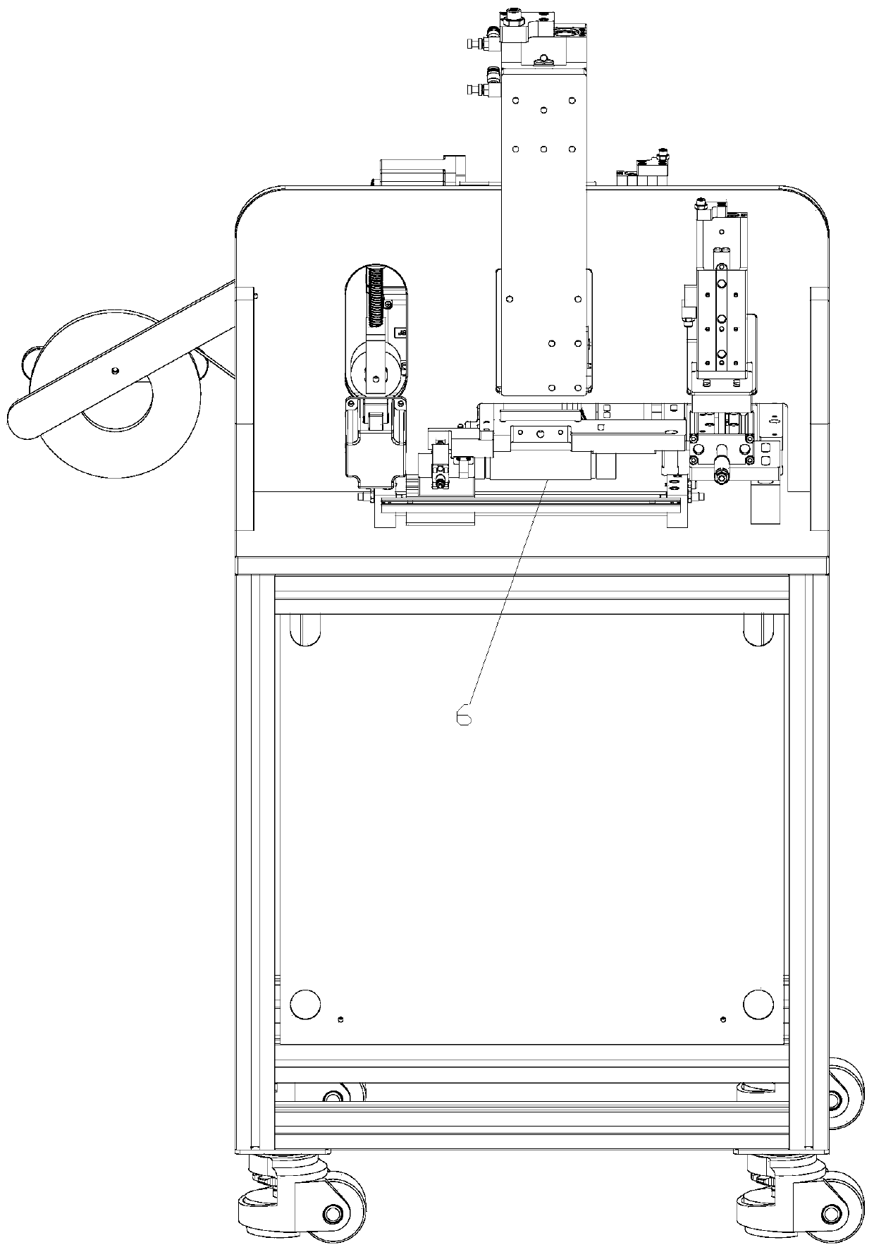
[0096] Automatic cartridge sealer, such as Figure 1~4 Shown, comprise frame 9, machine table 10, first guide mechanism 5, second guide mechanism 6, ironing mechanism 1, unwinding mechanism 81, pressing mechanism 83 and first delivery mechanism 3, frame 9 is located at On the machine table 10, the first guide mechanism 5 includes a first push plate 51 and a first guide member, the first guide member is used to push the first push plate 51 to move along the length direction of the machine table 10, and the second guide mechanism 6 includes a first push plate 51 to move along the length direction of the machine table 10. Two push plates 61 and a second guide, the second guide is used to push the second push plate 61 to move along the width direction of the machine table 10, the ironing mechanism 1 is located between the first push plate 51 and the second push plate 61, The cutting mechanism 2 includes a cutting piece and a cutting guide. The cutting guide is used to push the cut...

Embodiment 2

[0100] On the basis of Example 1, such as Figure 1~2 As shown, the first guide mechanism 5 also includes a third guide, the third guide includes a third cylinder 53 and a first moving plate 54, the third cylinder 53 is arranged on the frame 9 and arranged along the up and down direction, the third cylinder 53 is connected with the first moving plate 54 to push the first moving plate 54 to move up and down, and the first moving plate 54 is provided with a first guide piece.

[0101] As its preferred embodiment, the first guide is a first cylinder 52, the first cylinder 52 is arranged along the length direction of the machine, and the first cylinder 52 is connected with the first push plate 54 to push the first push plate 54 along the length of the machine 10. movement in the length direction.

[0102] In this embodiment, under the action of the third cylinder, the first moving plate can move up and down, thereby driving the first cylinder and the first push plate connected wi...

Embodiment 3

[0104] On the basis of embodiment 2 or its preferred embodiment, as Figure 3-4 As shown, the second guide mechanism 6 also includes a first guide rail 62, the first guide rail 62 is arranged on the machine platform and arranged along the length direction of the machine platform, the first guide rail 62 is provided with a second moving plate 63, and the second moving plate 63 is provided with a second guide.

[0105] As its preferred embodiment, the second guide includes a second guide rail 64, a guide block 65 and a second cylinder 66, the second guide rail 64 is arranged on the second moving plate 63 and is arranged along the width direction of the machine table, and the guide block 65 Located on the second guide rail 64 , the second air cylinder 66 is arranged along the width direction of the machine, and the second air cylinder 66 is connected with the guide block to push the guide block to move along the second guide rail 64 .

[0106] In this embodiment, when the fixed ...


PUM


Abstract

The invention relates to an automatic ink box sealing device. The automatic ink box sealing device comprises a rack, a machine table, a first guide mechanism, a second guide mechanism, an ironing mechanism, an unrolling mechanism, a pressing mechanism and a first conveying mechanism, wherein the first guide mechanism comprises a first pushing plate and a first guide part; the first guide part is used for pushing the first pushing plate to move in a length direction of the machine table; the second guide mechanism comprises a second pushing plate and a second guide part; the second guide part is used for pushing the second pushing plate to move in a width direction of the machine table; the ironing mechanism is positioned between the first pushing plate and the second pushing plate; the cutting mechanism comprises a cutting part and a cutting guide part; the cutting guide part is used for pushing the cutting part to move in the horizontal direction; and the unrolling mechanism is used for mounting an aluminum film roll; and the unrolling mechanism, the pressing mechanism, the cutting part and the ironing mechanism are sequentially arranged. The automatic ink box sealing device is high in working efficiency, is good in sealing effect, can save a great seal of manpower and material resources, and is high in popularization value.

Description

technical field [0001] The invention relates to the field of printing consumables, in particular to an automatic ink box sealing device. Background technique [0002] Ink cartridges mainly refer to the components used to store printing ink in inkjet printers and finally complete printing. At present, in the production process of the ink cartridge, it is necessary to assemble the parts, then fill the assembled ink cartridge with ink, and finally seal the ink cartridge with an aluminum film. The whole production process is relatively cumbersome, and the current production requires a lot of manual labor to complete each process of ink cartridge production on the ink cartridge production line. This production method not only requires a large number of people, but also the continuous operation of the assembly line greatly increases the fatigue of the staff. Further, the production efficiency of the ink cartridge is unsatisfactory. In addition, before the artificial use of alumin...

Claims


Application Information

Patent Timeline
IPC IPC(8): B65B7/16B65B51/14B65B61/06
CPCB65B7/164B65B51/144B65B61/06
Inventor 赵晨海
Owner 北海绩迅科技股份有限公司
Learn More