Supercharge Your Innovation With Domain-Expert AI Agents!

Hydraulic petroleum pipe lifting, carrying and mounting equipment

A technology for oil pipelines and installation equipment, applied in the field of hydraulic oil pipeline hoisting, handling and installation equipment, can solve problems such as low handling efficiency, and achieve the effect of increasing hoisting and conveying efficiency

Active Publication Date: 2019-08-06
CHINA UNIV OF PETROLEUM (EAST CHINA)
View PDF7 Cites 1 Cited by
  • Summary
  • Abstract
  • Description
  • Claims
  • Application Information

AI Technical Summary

Problems solved by technology

The device realizes the lifting of oil pipelines of different diameters through the mutual cooperation between the two clamping rings, which effectively avoids the left and right shaking of the oil pipeline during the lifting process, so that the oil pipeline can be sent to the installation position in preparation , and also reduce the labor intensity of workers, but the device can only handle one pipe at a time, and the handling efficiency is low

Method used


Image

  • Hydraulic petroleum pipe lifting, carrying and mounting equipment
  • Hydraulic petroleum pipe lifting, carrying and mounting equipment
  • Hydraulic petroleum pipe lifting, carrying and mounting equipment

Examples


Embodiment 1

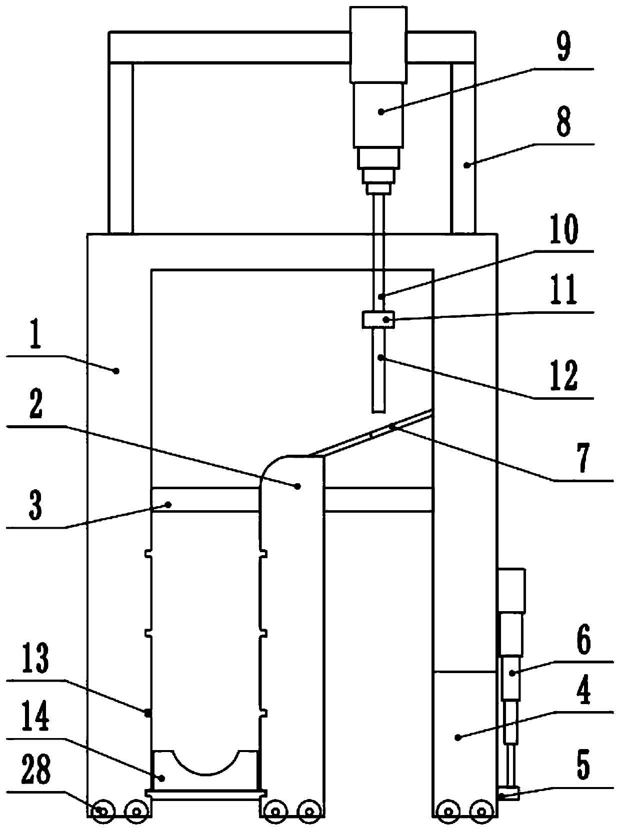
[0025] see Figure 1-5 , a hydraulic oil pipeline lifting, handling and installation equipment, comprising a hoisting frame 1, an isolation frame 2 is arranged inside the hoisting frame 1, a fixed rod 3 is fixedly connected between the isolation frame 2 and the hoisting frame 1, and the top of the hoisting frame 1 is fixedly connected The top frame 8 is fixedly connected to the second hydraulic telescopic rod 9. The hoisting frame 1 includes two legs, one of which is rotatably connected to the rotating leg 4, and the side of the rotating leg 4 away from the spacer 2 is slidably connected. The slider 5 is connected to the first hydraulic telescopic rod 6 in rotation, the first hydraulic telescopic rod 6 is fixedly connected to the hoisting frame 1, and a placement device 14 is provided between the other leg of the hoisting frame 1 and the isolation frame 2, and Both the hoisting frame 1 and the isolation frame 2 are provided with a draw-in slot 13 corresponding to the placement...

Embodiment 2

[0032] see Figure 1-5 , The other content of this embodiment is the same as that of Embodiment 1, except that the cross section of the placement groove 31 is semicircular, and the bottom ends of the lifting frame 1 and the isolation frame 2 are provided with moving wheels 28 .

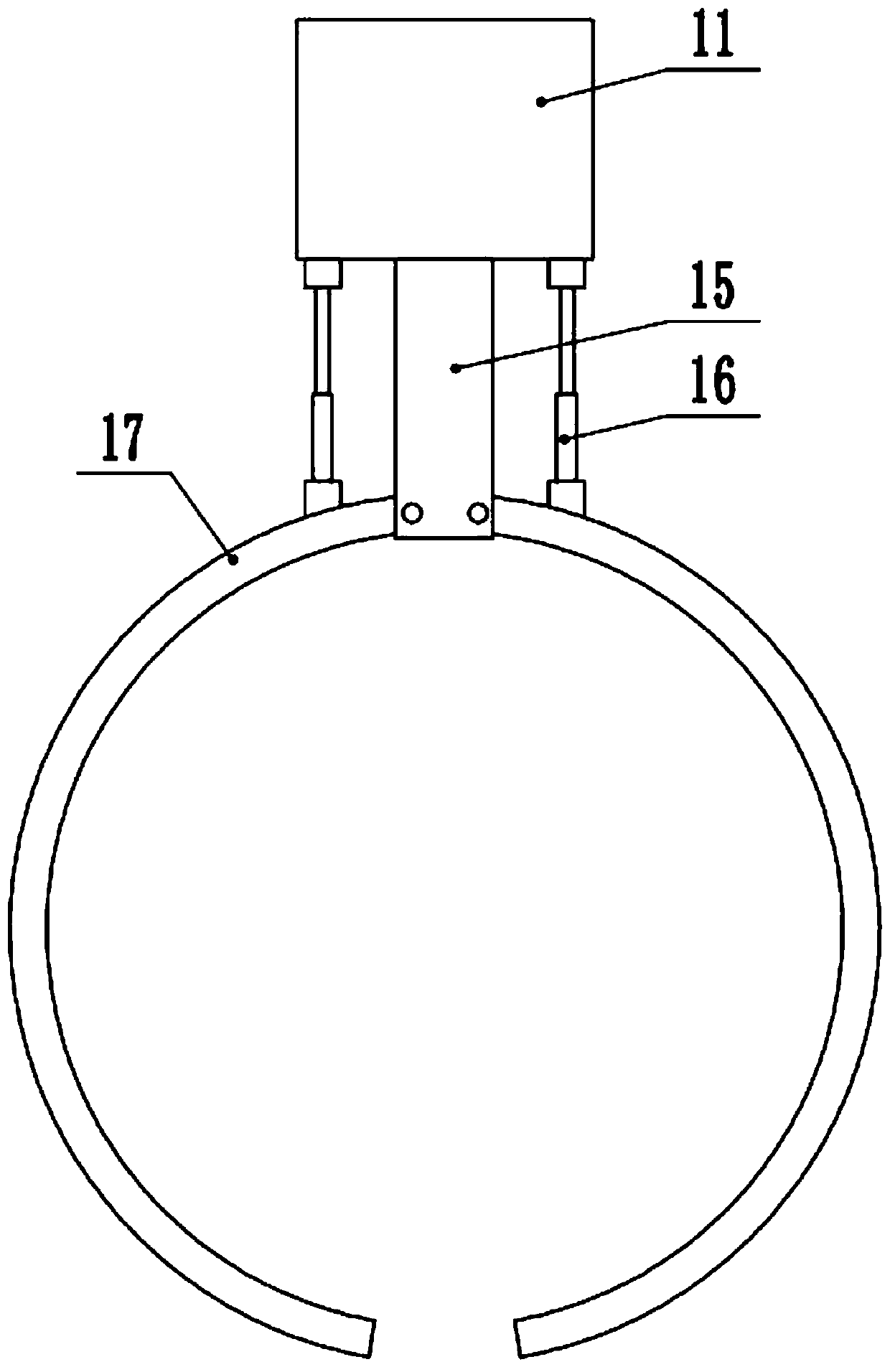
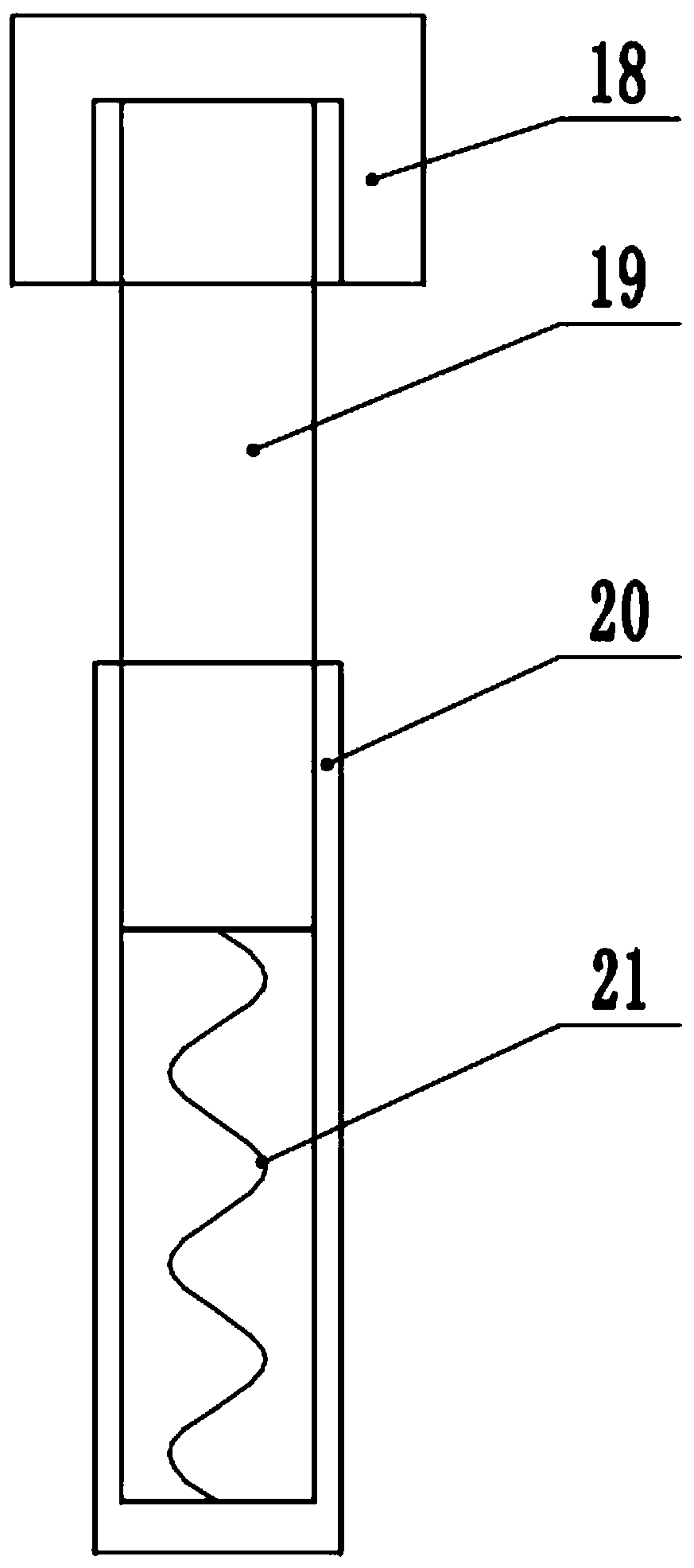
[0033] In the implementation process of the present invention, first start the first hydraulic telescopic rod 6 to rotate the rotating leg 4, so that the oil pipeline is placed on one side of the isolation frame 2, and then start the second hydraulic telescopic rod 9 to extend the clamping mechanism 12 Then, place the two jaws 17 on both sides of the oil pipeline, then insert the telescopic column 19 into the limit cap 18 to fix the jaws 17, and then start the second hydraulic telescopic rod 9 to shrink it so that the oil pipeline Lifting, the oil pipeline pushes the first rotating plate 24 and the second rotating plate 25 to rotate until it is located at the top of the hoisting frame 1 during the asc...


PUM


Abstract

The invention discloses hydraulic petroleum pipe lifting, carrying and mounting equipment, and relates to the technical field of petroleum pipe installation. The equipment comprises a lifting frame; an isolation frame is arranged in the lifting frame; a fixed rod is fixedly connected between the isolation frame and the lifting frame; a top frame is fixedly connected to the top end of the lifting frame; the top frame is fixedly connected with a second hydraulic extension rod; the lifting frame comprises two support legs, wherein one support leg is rotationally connected with a rotary support leg; the side, far from the isolation frame, of the rotary support leg is slidingly connected with a slide block; the slide block is rotationally connected with a first hydraulic extension rod; the first hydraulic extension rod is fixedly connected with the lifting frame; and a placing device is arranged between the other support leg of the lifting frame and the isolation frame. The equipment is provided with the second hydraulic extension rod and the clamping mechanism for clamping and lifting petroleum pipes, and is provided with the placing device for placing the lifted petroleum pipes; and multiple petroleum pipes can be placed, so that the lifting and conveying efficiency of the petroleum pipes is improved.

Description

technical field [0001] The invention relates to the technical field of oil pipeline installation, in particular to hydraulic oil pipeline lifting, handling and installation equipment. Background technique [0002] Petroleum, also known as crude oil, is a viscous, dark brown (sometimes greenish) liquid. There are oil reserves in parts of the upper crust. The nature of petroleum varies with the place of origin, the viscosity range is very wide, the freezing point varies greatly (30-60 degrees Celsius), the boiling point ranges from room temperature to above 500 degrees Celsius, it is soluble in many organic solvents, insoluble in water, but can form with water Emulsions, but the composition and appearance of oil from different oil fields can be very different. [0003] Oil relies on oil pipelines to transport oil. When oil pipelines are installed, lifting devices are often required to hoist the oil pipelines to the installation height for installation. Most of the traditiona...

Claims


Application Information

Patent Timeline
Patent Type & Authority Applications(China)
IPC IPC(8): B66D3/00B66C1/44
CPCB66C1/44B66D3/00
Inventor 黄鲁蒙高照张彦廷王培旺沈蓉王静
Owner CHINA UNIV OF PETROLEUM (EAST CHINA)
Features
  • R&D
  • Intellectual Property
  • Life Sciences
  • Materials
  • Tech Scout
  • Unparalleled Data Quality
  • Higher Quality Content
  • 60% Fewer Hallucinations
Learn More