Auxiliary slinging device and method through combination process of a plurality of cranes

A lifting device and combined operation technology, applied in cranes, transportation and packaging, etc., can solve the problems of weakened anti-instability, reduced lifting capacity, increased self-weight, etc., so as to improve stability and safety, reduce slewing Inertial force, the effect of enhancing dynamic stability

Active Publication Date: 2015-09-23
CHINA UNIV OF MINING & TECH
View PDF6 Cites 8 Cited by
  • Summary
  • Abstract
  • Description
  • Claims
  • Application Information

AI Technical Summary

Problems solved by technology

[0003] The joint hoisting of multiple cranes can greatly increase the lifting capacity and operating radius, but it is necessary to increase the length and number of sections of the main boom, and in some cases even increase the lattice jib. An overly long boom will generate a large bending moment, and the self-weight increase, the lifting capacity will be greatly reduced. The existing technology is to increase the super-lifting device, but as the working radius increases, the boom increases, the effective component force of the super-lifting device on the boom decreases, and the anti-stabilization ability weakens. At the same time, the operation process is mainly done manually, which is prone to improper load distribution and unreasonable coordination strategies, which greatly increases the danger. Moreover, the crane is only supported by its own hydraulic outriggers. Once an accident occurs to one crane, it will inevitably cause other accidents. Sudden changes in the stress of crane wire ropes, resulting in major chain accidents

Method used


Image

  • Auxiliary slinging device and method through combination process of a plurality of cranes
  • Auxiliary slinging device and method through combination process of a plurality of cranes
  • Auxiliary slinging device and method through combination process of a plurality of cranes

Examples


Embodiment Construction

[0019] The present invention will be further explained below in conjunction with the accompanying drawings.

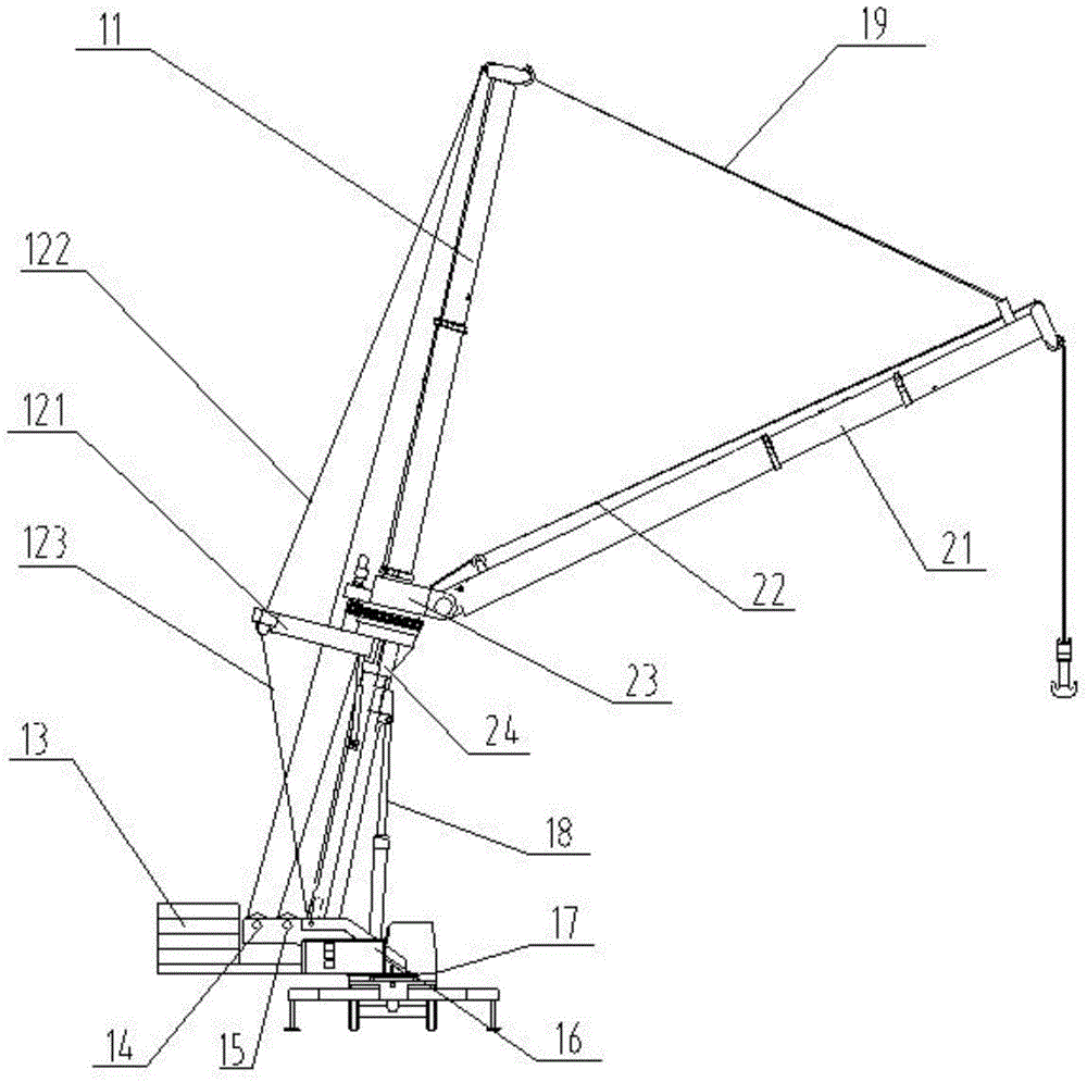
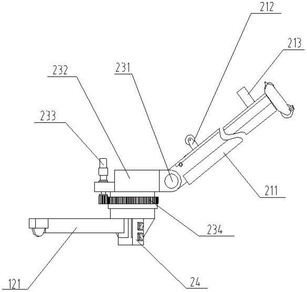
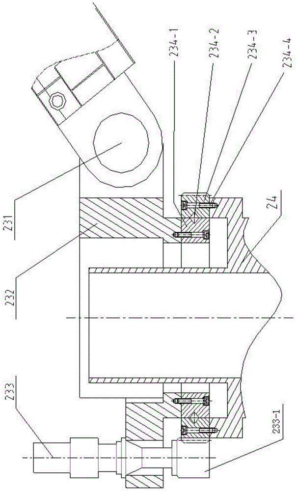
[0020] Such as figure 1 , 2 Shown in and 4, the crane 1 that is equipped with auxiliary hoisting device 2 of the present invention comprises getting off the car 17, is provided with turntable 16 on the car 17, is provided with counterweight 13, main boom 11 and main winch 14 on the turntable 16, main The boom 11 is provided with a super-lifting device 12 and a luffing oil cylinder 18 , and the main hoist 14 is wound with a main suspension rope 19 . The auxiliary lifting device 2 of the present invention includes an auxiliary winch 15 , a telescopic auxiliary boom 21 , an auxiliary lifting rope 22 , a rotatable auxiliary slewing support 23 , a connection base 24 and a crane connection device 4 . The connection base 24 is fixedly connected to the main boom 11 by bolts, and the auxiliary slewing support 23 is rotatably connected to the connection base 24 . The auxiliar...


PUM


Abstract

The invention discloses an auxiliary slinging device and method through combination process of a plurality of cranes. The auxiliary slinging device comprises an auxiliary winch, an elastic auxiliary suspension arm, an auxiliary suspension rope, a turnable auxiliary rotation support, a connecting base and a connecting device for the cranes, wherein the connecting base is connected with main suspension arms of the cranes; the auxiliary rotation support is connected with the connecting base, and the arm tail of the auxiliary suspension arm is hinged to the auxiliary rotation support; the auxiliary wince is arranged on a rotary table of each crane, the auxiliary suspension rope winds the auxiliary winch , and the auxiliary suspension rope winds around the arm head of the auxiliary suspension arm; the main suspension ropes of the cranes wind around the arm head of the main suspension arm to be connected with the auxiliary suspension arm; the connecting device for the cranes is connected with the connecting base, and the auxiliary hoisting method adopts the auxiliary slinging device to sling heavies. The auxiliary slinging device and method, disclosed by the invention, can realize hoist in a large working space for the cranes under the condition of not enlarging the length of an elevating arm, so that the destabilizing resistance and the hoisting stability of the cranes are improved, and the hoisting efficiency is improved.

Description

technical field [0001] The invention relates to the technical field of cranes, in particular to an auxiliary lifting device and method for combined operations of multiple cranes. Background technique [0002] With the continuous expansion of petrochemical, nuclear power, metallurgy and other construction scales, the key equipment used in the project is developing towards extra large and extra heavy. In order to pursue higher efficiency and benefits, overall hoisting projects are becoming more and more common. Hoisting equipment and The requirements for hoisting technology are also getting higher and higher. Heavy equipment such as reactors, domes for nuclear power plants, and storage oil pipes have large diameters, heavy weights, and high heights. When hoisting, lifting equipment is required to have strong hoisting capacity. At the same time, it has a large working space and is difficult to hoist. At present, the hoisting of large-scale equipment is mostly done by tower cra...

Claims


Application Information

Patent Timeline
Patent Type & Authority Applications(China)
IPC IPC(8): B66C23/06B66C23/64B66C23/84
CPCB66C23/06B66C23/64B66C23/84B66C2700/03
Inventor 杨善国訾斌贾宁钱森
Owner CHINA UNIV OF MINING & TECH
Why Eureka
Try Eureka