A device for handling a yarn end, a method, and an annular spinning machine

A ring spinning machine, yarn technology, applied in the field of yarn end and sucking the yarn end into the mouth of the suction tube, which can solve the limitation of size and mobility of transfer equipment, small space, etc. problem, to achieve the effect of guaranteed layout, low weight, good durability

Active Publication Date: 2019-08-06
MASCHINENFABRIK RIETER AG
View PDF11 Cites 1 Cited by
  • Summary
  • Abstract
  • Description
  • Claims
  • Application Information

AI Technical Summary

Problems solved by technology

[0005] There is very little space at the spinning stations of the ring spinning machine, since the spacing between the spinning stations is, for example, only 70 or 75 mm, and the requirements in terms of size and mobility therefore place great demands on the transfer equipment. considerable restrictions

Method used


Image

  • A device for handling a yarn end, a method, and an annular spinning machine

Examples


Embodiment Construction

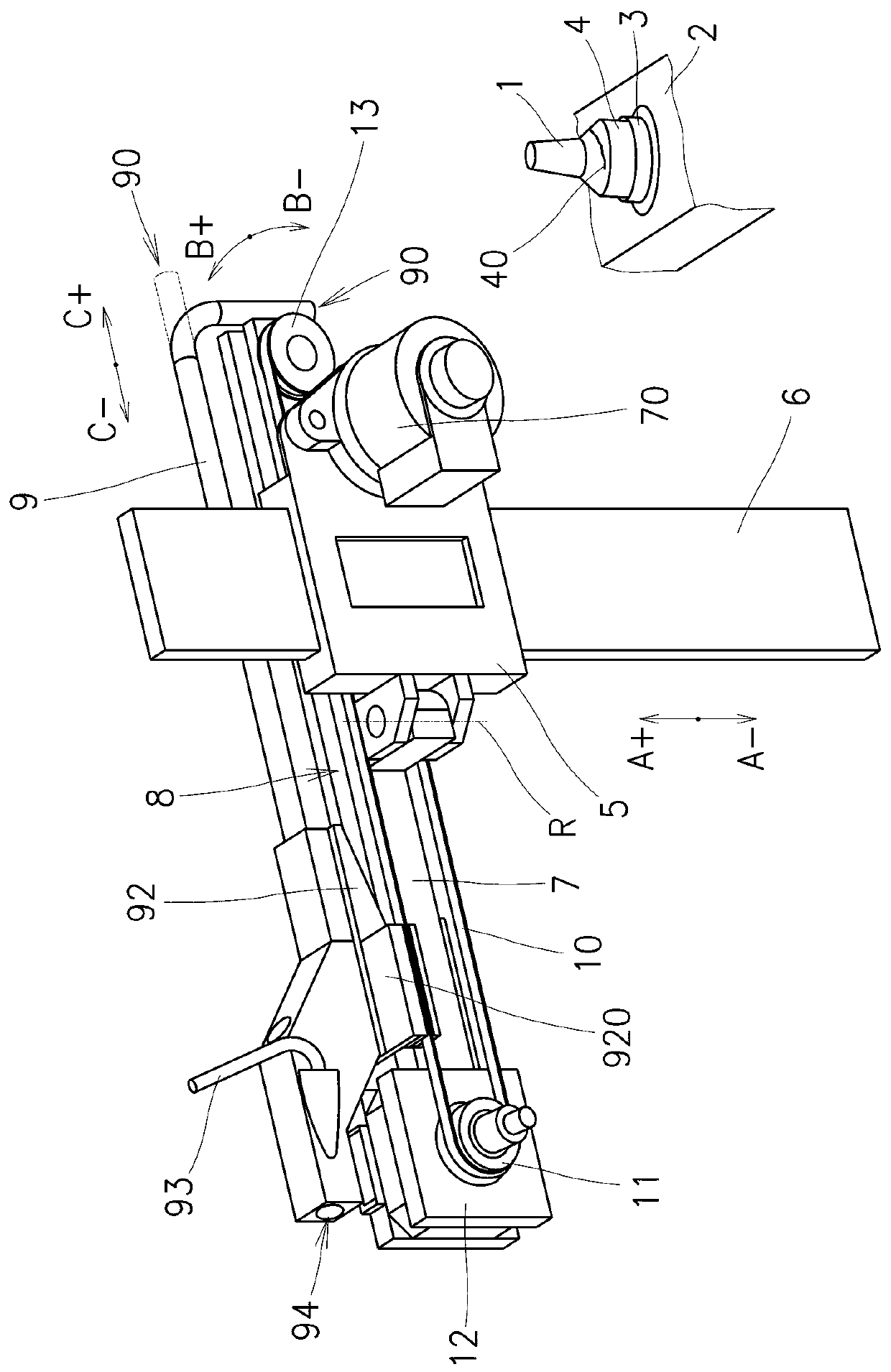
[0024] The invention will be described with reference to an exemplary embodiment of a yarn end transfer device at a spinning station (also understood as spinning unit) of a ring spinning machine.

[0025] A ring spinning machine comprises a row of identical spinning stations arranged next to each other. In principle, spinning stations are well known and therefore the entire spinning station will only be described in a simplified manner below. Those parts, elements and nodes of the spinning station which are of significance to the invention will be described in more detail. The spinning station comprises a roving drafting device, not shown, below which the yarn twisting and winding device is arranged. The roving is fed from a supply package, not shown, to the drafting device, after which the formed yarn passes through the guide eyelets, the balloon containment shield and then through the traveler which surrounds the ring 3 around the circumference of the flange, the ring 3 is...


PUM


Abstract

The invention relates to a device for handling a yarn end, a method, and an annular spinning machine. The device for handling a yarn end (40) at the spinning point of an annular spinning machine afterlocating the yarn end (40) on the spool comprises a suction pipe (9) with a suction mouth (90) assignable to the spinning location, the suction pipe (9) is connected to a vacuum source where the suction pipe (9) is mounted on a positioning system to guide the mouth (90) of the suction pipe (9) to the pulling device of the spinning station to recover the spinning process. The positioning system contains a support part (5) which is linearly reciprocally mounted on a vertical guide (6), a horizontal arm (7) which reciprocally pivots about the vertical axis (R) on the support part (5), and a suction tube (9), on the horizontal arm (7) linearly reciprocating in the horizontal direction (C +, C-).The invention also relates to a method of handling a yarn end (40) and an annular spinning machine.

Description

technical field [0001] The invention relates to a yarn end handling device (or "handling device") at a spinning station of a ring spinning machine for detecting a yarn end on a bobbin that The transfer device comprises a suction tube with a suction mouth assignable to the spinning station, the suction tube is connected to a vacuum source, whereby the suction tube is mounted on a positioning system for the positioning of the suction tube The mouth leads to the drafting unit of the spinning station for the recovery of the spinning process. [0002] The invention also relates to a device according to the invention at the spinning unit of a ring spinning machine after finding the yarn end on the bobbin and sucking the yarn end into the mouth of the suction pipe. Method for transferring yarn ends, wherein the mouth of the suction pipe guides the yarn ends back to the drafting device of the spinning station for the recovery of the spinning process. [0003] Furthermore, the invent...

Claims


Application Information

Patent Timeline
Patent Type & Authority Applications(China)
IPC IPC(8): D01H15/013
CPCD01H15/013D01H13/00D01H15/00
Inventor M.莫拉维克T.布洛泽克
Owner MASCHINENFABRIK RIETER AG
Why Eureka
Try Eureka