Stud for tyre

A tire and nail clip technology, applied in special tires, tire parts, tire treads/tread patterns, etc., can solve the problem of not being able to use studs, and achieve the effect of reducing waste ratio and light weight

Inactive Publication Date: 2008-06-25
TURVANASTA
View PDF7 Cites 1 Cited by
  • Summary
  • Abstract
  • Description
  • Claims
  • Application Information

AI Technical Summary

Problems solved by technology

In this type of stud, the shank is significantly narrower than the base, so that the same devices used to install ordinary studs cannot be used to install this type of stud

Method used


Image

  • Stud for tyre
  • Stud for tyre

Examples


Embodiment Construction

[0019] The present invention is explained by examples below in conjunction with the accompanying drawings.

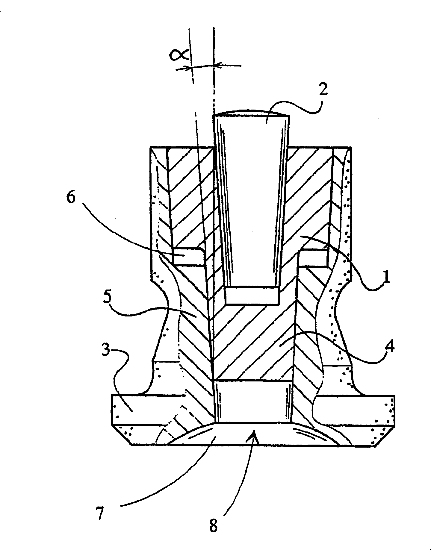
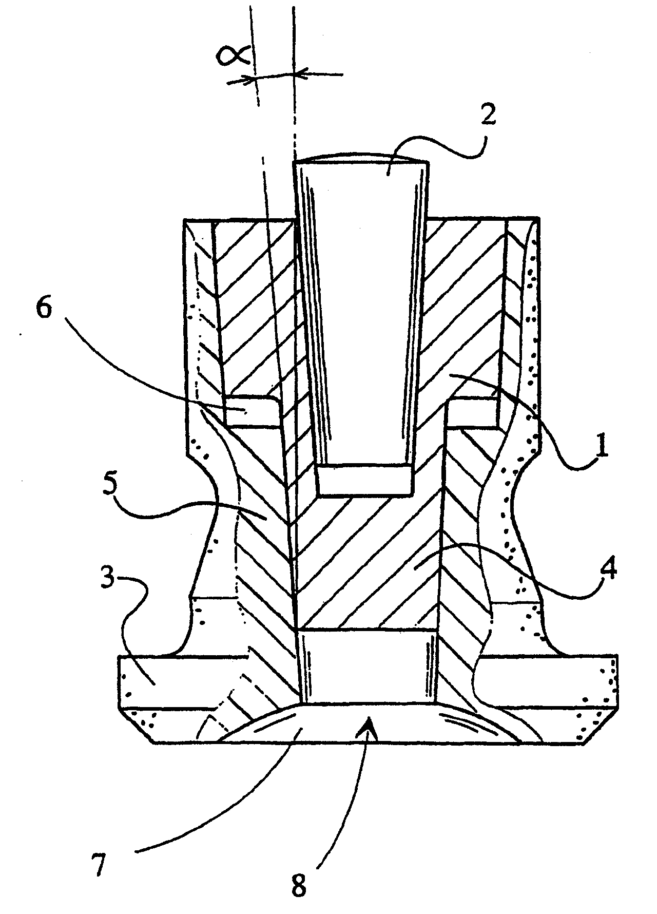
[0020] The stud comprises a socket-shaped body part 1 with a hard metal tip 2 at one end. At its other end, the body has a locking flange 3 which clamps the stud in the tire. The locking flange 3 is made of plastic. The stud body part 1 has a pin 4 extending towards the locking flange, on the upper part of which a tubular sleeve part 5 of the locking flange is fixed. The body part 1 is tapered to clamp as a wedge in a corresponding tapered sleeve part 5 . The body part 1 has a graduated tapered surface, the diameter of which is greater at the hard metal tip 2 than at one end 4 of the locking flange 3 . At the stepped position of the tapered surface of the body part 1 and at the stepped position of the tapered surface of the sleeve part 5 there is a hollow annular space 6 which allows the body part 1 to be wedged when pressure is applied to the stud Go deeper. The g...


PUM


Abstract

The invention relates to a stud for a tyre comprising a socket-formed body portion ( 1 ), having at one end a hard metal peak ( 2 ) and at its other end a locking flange ( 3 ) retaining the stud in the tyre and being made of a light injection-mouldable material, such as plastic, the body portion ( 1 ) having a pin ( 4 ) extending towards the locking flange, with the tubular sleeve portion ( 5 ) of the locking flange fixed on top of this pin. The body portion ( 1 ) is conical so as to be clamped as a wedge into the corresponding conical sleeve portion ( 5 ).

Description

technical field [0001] The present invention relates to a stud for a tire comprising a socket-shaped body portion having a hard metal tip at one end and a locking flange at the other end to retain the stud in the tire, the locking flange being formed by a Made of lightweight material, such as plastic, the body portion has a pin extending towards the locking flange with a tubular sleeve portion secured to the locking flange on top of the pin. Background technique [0002] Generally, manufacturers of winter tires try to reduce the amount of rubber used in tires, in order to reduce the weight and enhance the grip characteristics (grip characteristics) on the road surface without making them hang up in the vehicle. Winter tires with light winter tire studs also cause less wear on the pavement material. The stud locking lugs of light winter tires taper towards the plies of wire mesh inside the winter tire during use. Such a result is that when the stud is tilted, the edge of th...

Claims


Application Information

Patent Timeline
Patent Type & Authority Patents(China)
IPC IPC(8): B60C11/16B60C1/00
CPCB60C11/165
Inventor 赫基·撒拉卡里
Owner TURVANASTA
Why Eureka
Try Eureka