
Relocating data from end-of-life storage driver in data storage system using mapped RAID technology

A data storage system and relocation technology, applied in the input/output process of data processing, electrical digital data processing, instruments, etc., can solve the problem of time-consuming and resource-consuming storage processors, improve replication performance, increase parallelism the effect of reducing overall replication time

Active Publication Date: 2019-08-06
EMC IP HLDG CO LLC
View PDF5 Cites 3 Cited by
  • Summary
  • Abstract
  • Description
  • Claims
  • Application Information

AI Technical Summary

Problems solved by technology

[0008] Since the capacity of modern hard disks increases over time, responding to receipt of an "end of life" message from a data storage drive is a challenge to the data storage system by replicating the entire collection of data stored on the data storage drive to a single healthy data storage drive. has become very time-consuming and resource-intensive for storage processors

Method used


Image

  • Relocating data from end-of-life storage driver in data storage system using mapped RAID technology
  • Relocating data from end-of-life storage driver in data storage system using mapped RAID technology
  • Relocating data from end-of-life storage driver in data storage system using mapped RAID technology

Examples


Embodiment Construction

[0032] Embodiments of the present invention will now be described. It should be understood that the embodiments described herein are provided by way of example only in order to illustrate various features and principles of the disclosed technology and that the invention is broader than the specific embodiments described herein.

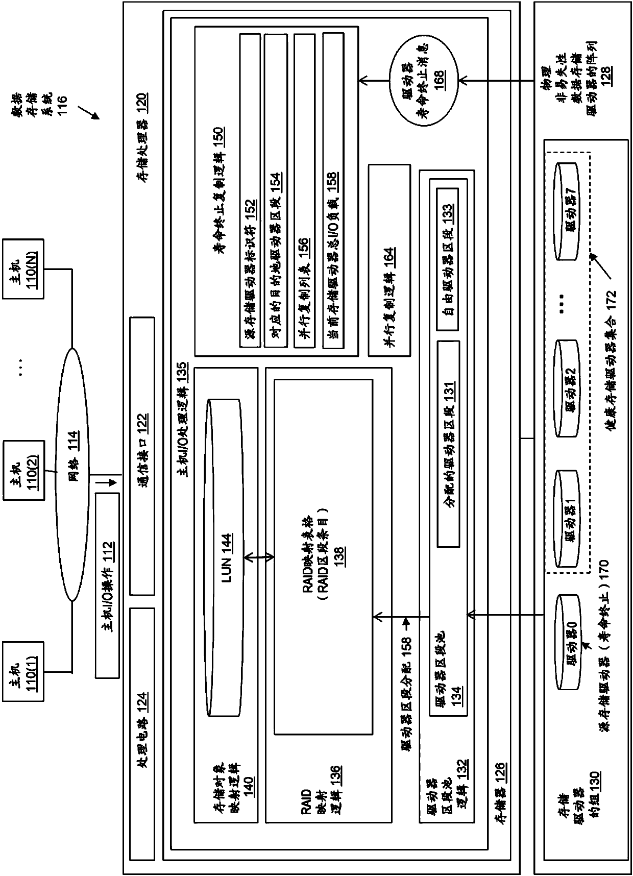
[0033] figure 1 is a block diagram illustrating an operating environment for the disclosed technology, including an example of a data storage system in which the disclosed technology may be embodied. figure 1 The operating environment includes some number of host computing devices 110, referred to as "hosts," and are shown for purposes of illustrating hosts 110(1) through 110(N), connected, for example, by one or more computer networks Access to data storage provided by data storage system 116, one or more computer networks such as a local area network (LAN) and / or a wide area network (WAN) such as the Internet, etc., at figure 1 Illustrated by netw...


PUM


Abstract

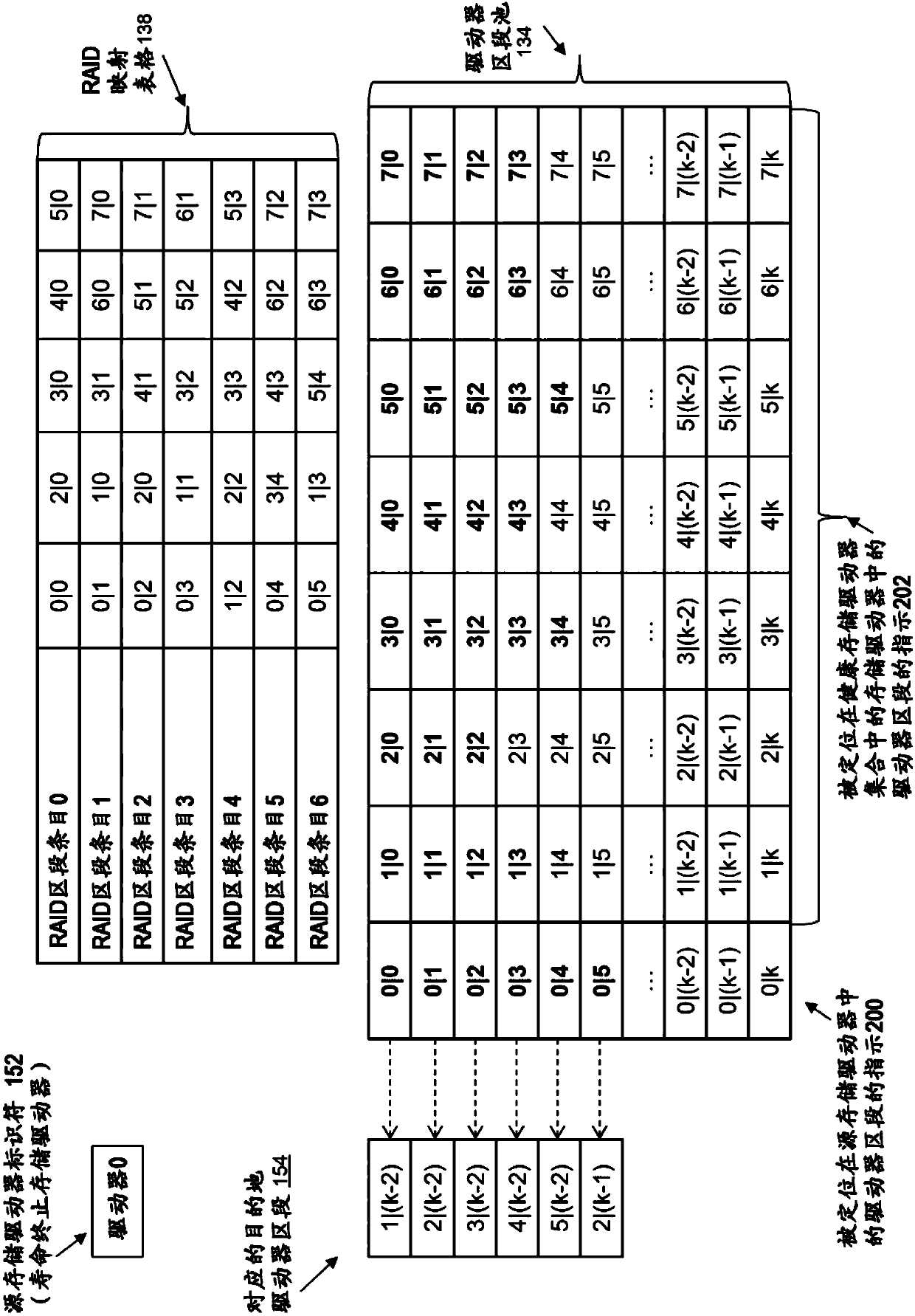
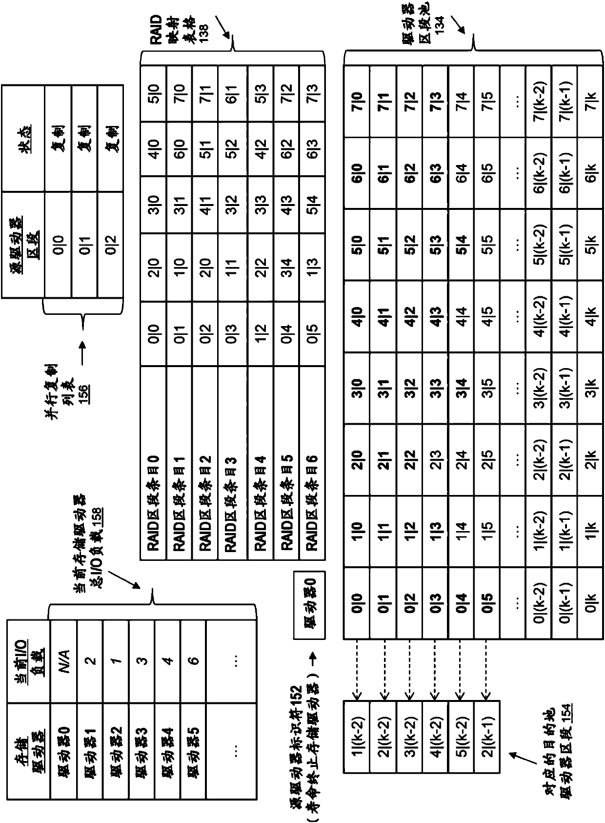
A technology for relocating the data stored in an end-of-life source storage driver is characterized in that an individual destination driver section corresponding to a driver section positioned in asource storage driver is identified by selecting the individual storage drivers within the set of the healthy storage drivers in the storage driver group in a cyclic manner and identifying the individual destination driver sections from each selected storage driver; the corresponding destination driver section replaces the driver section positioned in the source storage driver and is used to storethe data copied from the driver section positioned in the source storage driver, and the data is copied in parallel from a set of the plurality of driver segments positioned in the source storage driver to the storage driver where the corresponding destination driver segment is positioned, and the set of the plurality of driver segments is selected based on a current total input / output load determined for each of the set of the healthy storage drivers.

Description

technical field [0001] The present disclosure relates generally to intelligent data storage systems that provide RAID (Redundant Array of Independent Disks) technology, and more particularly to methods for relocating data from end-of-life storage based on storage drive load in data storage systems that use mapped RAID technology. drive data. Background technique [0002] A data storage system is an arrangement of hardware and software that typically includes multiple storage processors coupled to non-volatile data storage devices such as magnetic disk drives, electronic flash drives, and / or optical drives. The storage processor service hosts the I / O operations received from the host. The received I / O operations specify one or more storage objects (such as logical disks or "LUNs") to be written, read, created, or deleted. The storage processor runs software that manages incoming I / O operations and performs various data processing tasks to organize and protect host data rece...

Claims


Application Information

Patent Timeline
Patent Type & Authority Applications(China)
IPC IPC(8): G06F3/06
CPCG06F3/061G06F3/0616G06F3/0619G06F3/0655G06F3/0673G06F3/0647G06F3/067G06F3/0689G06F11/1076
Inventor 刘青云康剑斌龚绍钦孙蕾高健
Owner EMC IP HLDG CO LLC
Learn More